Straightside Servo Press DSF-M2 Progressive Die & Transfer, From 315 - 1,250 Tons

Press Information
Press Information & Overview
Maximized Servo Press Flexibility, Maximized Profits for Your Operations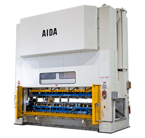
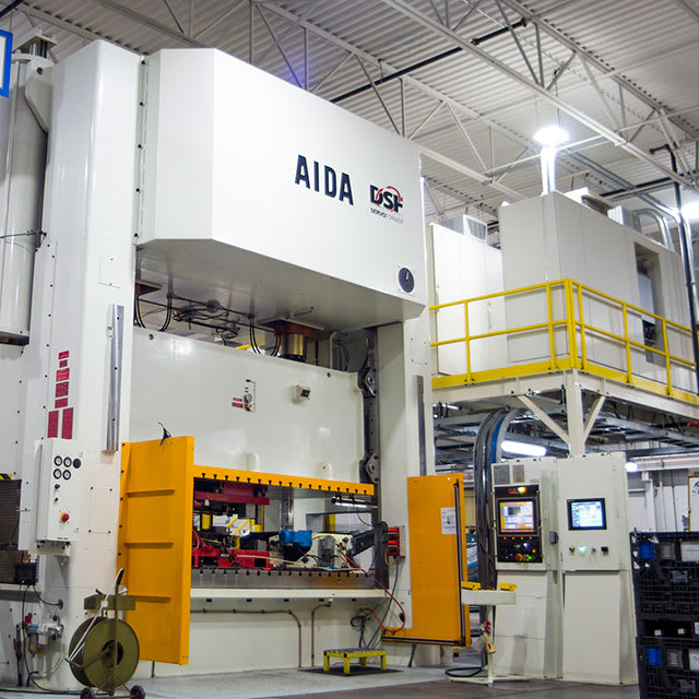
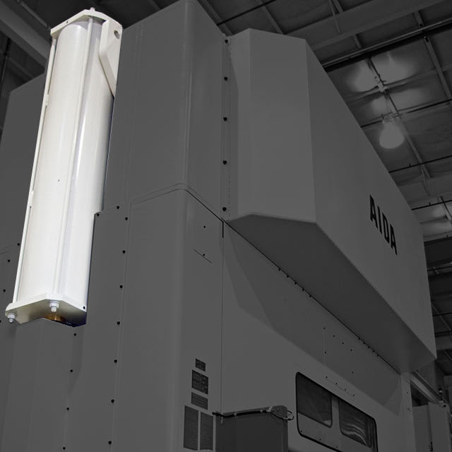
The AIDA DSF-M2, straightside tie-rod frame servo press manufactured in AIDA-America's 180,000 sq. ft. factory in Dayton, OH, is available from 315 through 1,250 tons capacity. Configurations include single or double reduction eccentric gear drive, 1/4" and 1/2" rating points, a wide variety of stroke length and die height choices as well as zero clearance roller-type slide guides (with bronze oil film guides as an option).
The DSF-M2, like all AIDA Direct Drive Servo Formers (DSF Series), includes the AIDA designed and manufactured direct drive high torque, low RPM servo motor specifically designed for stamping press applications.
Press Features
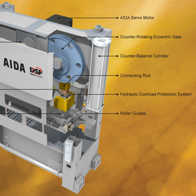
AIDA DSF-M2 Servo Press Features
- AIDA Servo Motor
![AIDA Servo Motor for Stamping Presses]()
- Wide Connections Spacing
![Wide Spaced Connections for Better Load Distribution]()
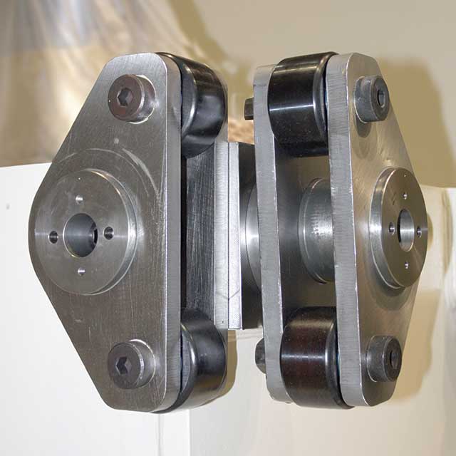
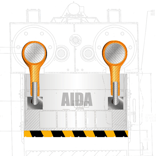
- Ball Socket Connection Points
![Ball and Socket Connection Points]()
- Fastest acting HOLP in the industry (10 ms)
![AIDA Hydraulic Overload Protection System (HOLP)]()
- Roller Guides
![Roller Guides]()
- Highly Rigid Frame
![Highly Rigid Frame]()

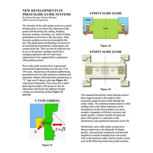
8-Point Roller Type Slide Guide System
 Zero-Clearance Guides and Lube Free Die Space
(8) points of eccentric pin adjustment allow easy setting to maintain slide to bolster parallelism of less than .001"/ft
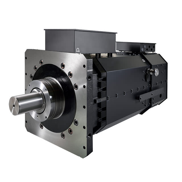
AIDA Servo Motors
 The Most Powerful Servo Motors Available for Stamping Presses
Direct drive servo motors, driving the industry's leading servo presses. Low speed, high torque, specifically manufactured for stamping press applications using standard press drive train design.
Ball and Socket Connections
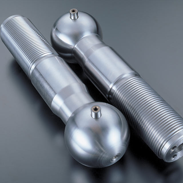 Improved Design When Compared to Wrist Pin Connections
Eliminate one of the largest maintenance costs of a stamping press: the wrist pin slide connections. Designed to withstand the rigors of heavy stamping.
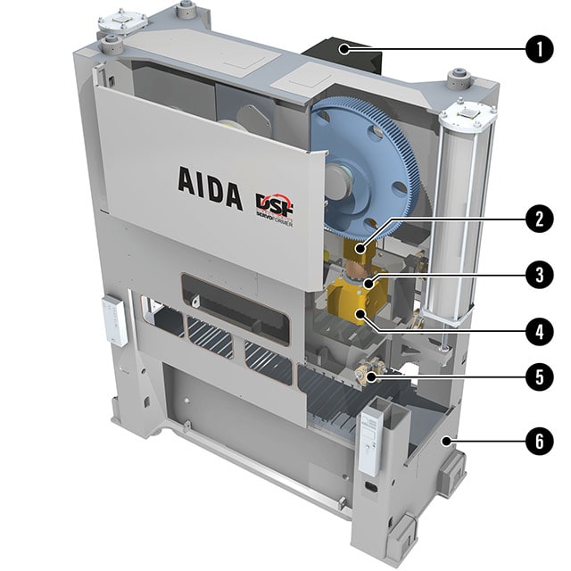
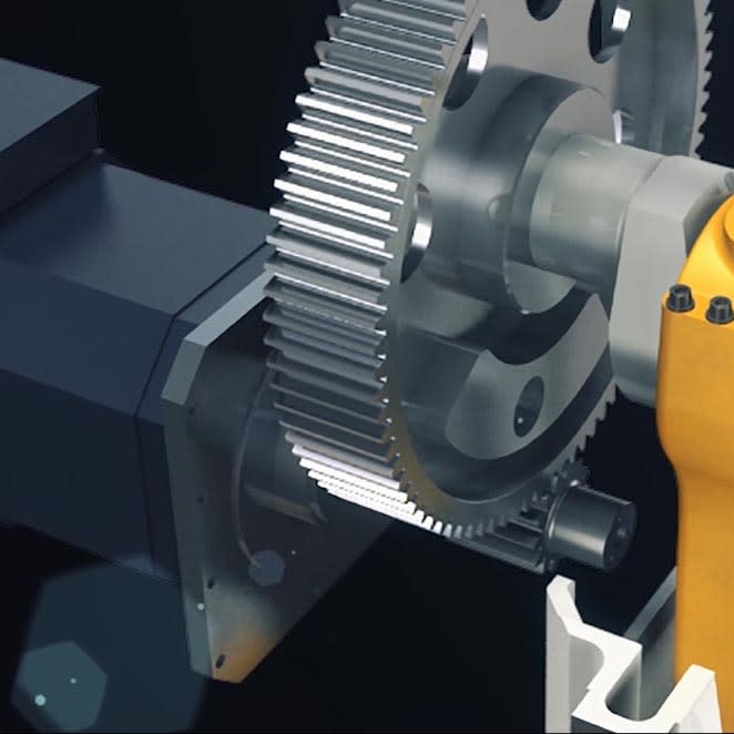
Eccentric Gear Drive
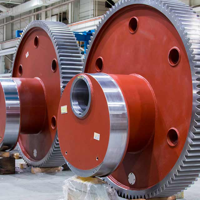 The Most Widely Used Drive System for Straightside Stamping Presses
Slide motion provided by eccentric lobes that are part of the main drive gears. Gears are mounted on pins that run front to back in the press crown.
HOLP
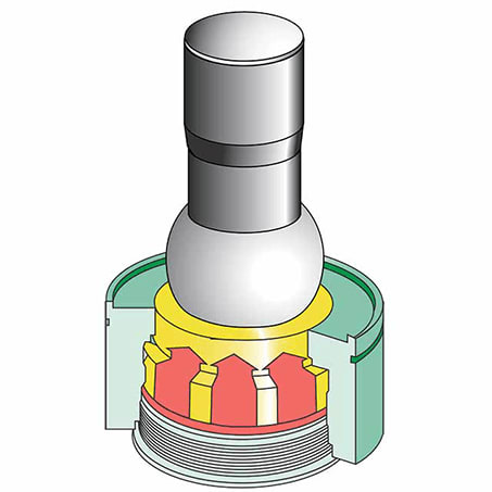 Hydraulic Overload Protection System
AIDA's press technology - the industry's fastest protection system. When overload occurs, oil evacuates 360 degrees around the ball seat with minimum oil flow resistance as compared to conventional systems
Highly Rigid Press Frame
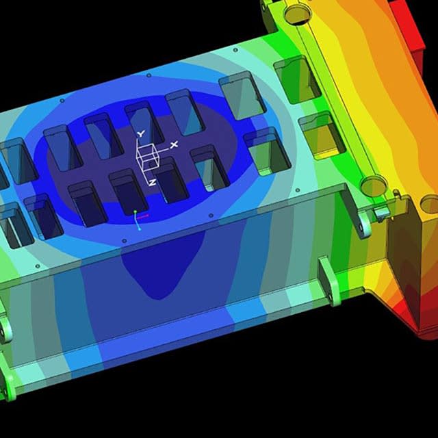 Reduced Frame Deflection for Higher Precision Metal Stamping
Frame components are massive steel fabrications to reduce deflection. Welded steel construction. FEA modeled design.
Self-Contained Counterbalances
 Low Maintenance System Improves Performance
Cylinder length provides additional volume, eliminating the need for surge tanks and related piping. Cylinder length is 5 times that of the press stroke
Wide Connections Spacing
 Increased Off-Center Load Bearing Capacity
Reducing the negative effects of off-center loading and providing greater freedom in die design & layout.
Servo Press Control Features
Allen-Bradley PLC
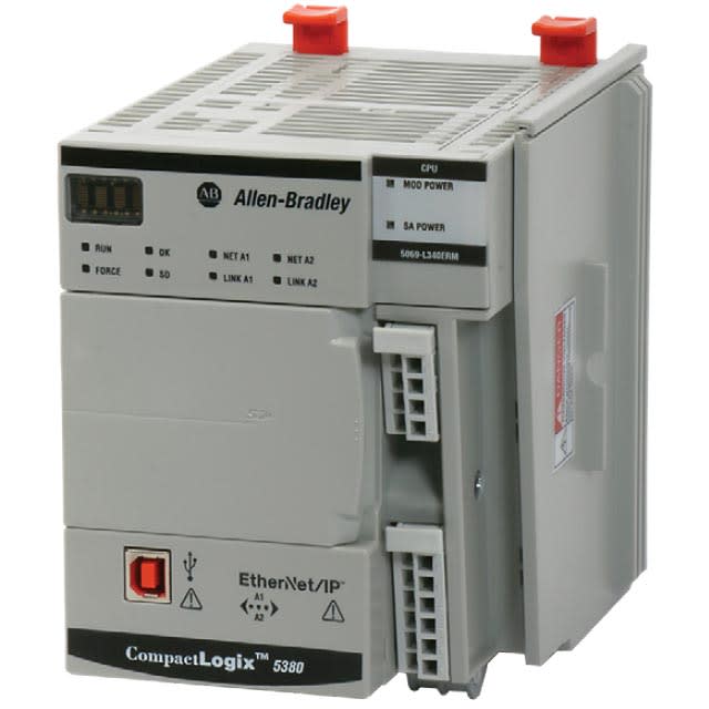 For Servo Presses 315 Tons and Above
CompactLogix PLC with Beckhoff motion controller for precise control. Locally designed and manufactured to meet North American customer needs.
More About Allen-Bradley PLC Servo Press ControlsCNC Handwheel Control
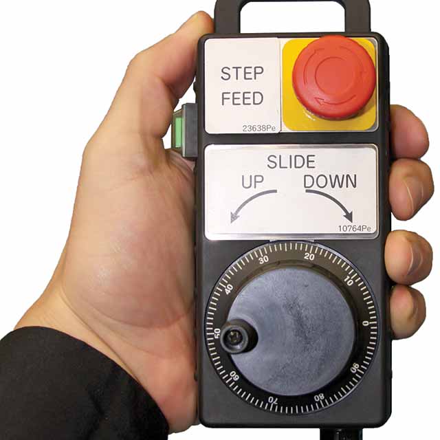 Handheld Type
 Precise control of your servo press at your fingertips. The answer to die set-up and try-out operations. Step Feed Mode, controlled by the handwheel, allows press operators to cycle the press at below 1 spm.
More About CNC Handwheel Control19" Color Touch Screen
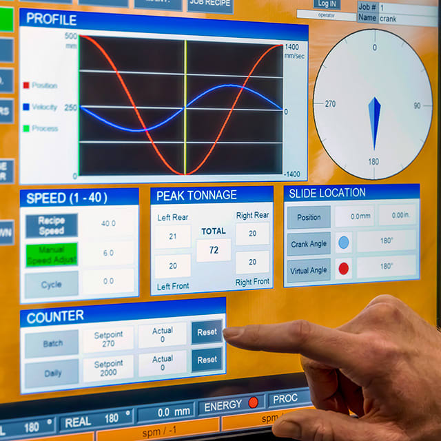
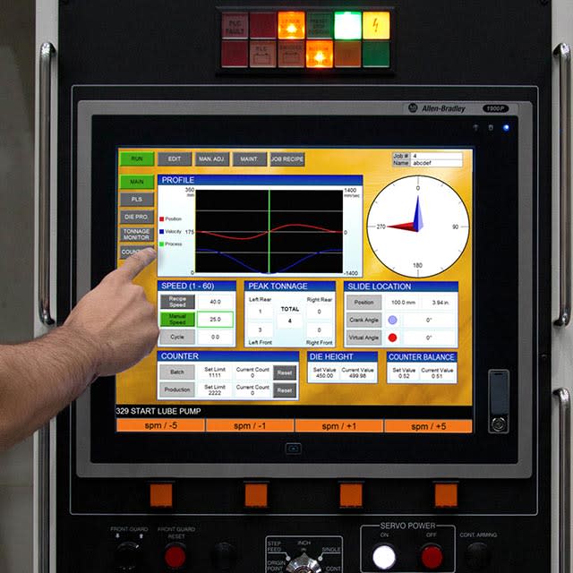 Easy to view and operate
19" color touch screen HMI with full motion profile display. Powered by an Allen-Bradley 1900P display computer.
Allen-Bradley GuardLogix
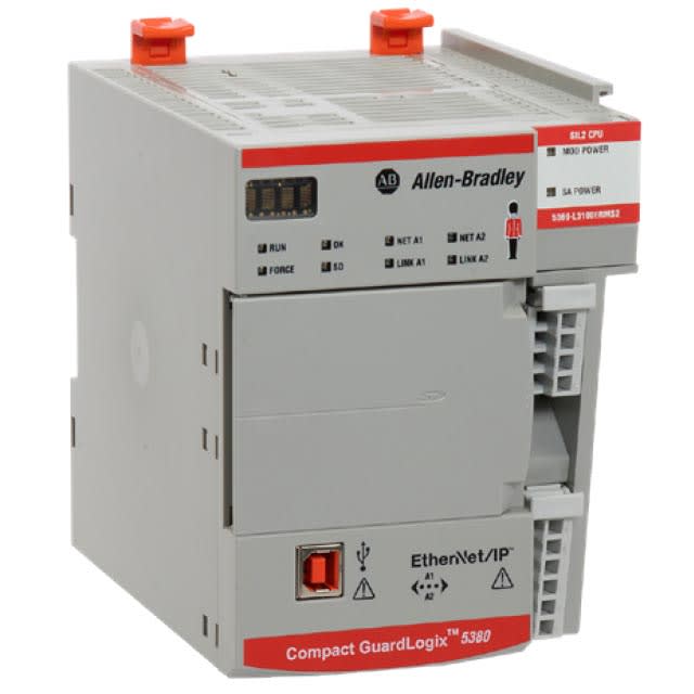 Integrated Safety Controller
Press safety enabled through the fully integrated Allen-Bradley GuardLogix safety controller PLC.
E.C.O. System
The most efficient servo press energy management system available. The AIDA system stores energy in long life capacitor system (rated over 20 years) to optimize energy consumption.
More About E.C.O. SystemProgrammable Slide Motions
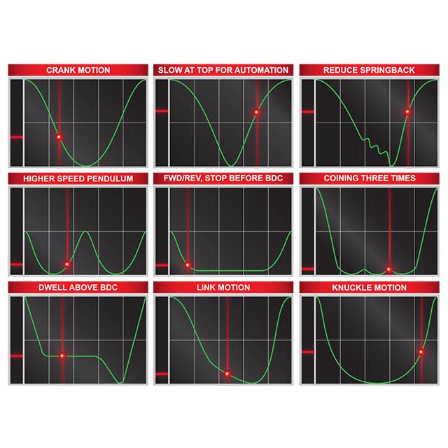 Complete Control of Position, Velocity, Dwell & Beyond
Optimized servo press slide motion profiles maximize metal stamping productivity and improve part quality.
- Additional DSF-M2 Servo Press Control Features
- Fully programmable stroke length, velocity, and dwell for optimized production for every die
- 500 Job Recipe Storage
- Teach function minimizes the possibility of operator entry error
- Redundant dual encoders for additional safety
- 16 channel PLS for improved safety and productivity
- Integrated Tonnage Monitor
- Third-Party Integration, with auxiliary equipment screens shown on press OIT
- Remote diagnostics capability with eWon provided by AIDA Engineering and Service teams
- Exceeds OSHA/ANSI/CSA safety standard requirements
Press Specifications
DSF-M2 Servo Press Specifications
| 315 Ton | 400 Ton |
| 630 Ton | 800 Ton |
| 1,000 Ton | 1,250 Ton |
| Specifications PDF | |
| 315 Ton | 400 Ton |
| 630 Ton | 800 Ton |
| 1,000 Ton | 1,250 Ton |
| Specifications PDF |
DSF-M2-3150, 315 Ton Servo Press Specifications
| DSF-M2-3150 MODELS (SERVO) | ||||
| Press Technical Data | Unit | Single Reduction | ||
| Capacity | kN | 3,150 | ||
| U.S. ton | 347 | |||
| Full Stroke Length | mm | 250 | 300 | 350 |
| in. | 9.8 | 11.8 | 13.8 | |
| Rating Point | mm / SPM | 7.7 @ 40 2.6 @ 50 | 6.4 @ 40 2.3 @ 50 | 5.2 @ 40 2.0 @ 50 |
| in. / SPM | 0.30 @ 40 0.10 @ 50 | 0.25 @ 40 0.09 @ 50 | 0.20 @ 40 0.08 @ 50 | |
| Die Height Options (SDAU) | mm | 600, 650, 700 or 750 | ||
| in. | 23.6, 25.6, 27.6 or 29.5 | |||
| Slide Adjustment | mm | 200 | ||
| in. | 7.9 | |||
| Slide and Bolster Area | mm | 3050 x 1500 | ||
| in. | 120.1 x 59.1 | |||
| Bolster Thickness | mm | 150 | ||
| in. | 5.9 | |||
| Max Upper Die Weight | kg | 3,000 | ||
| lb. | 6,600 | |||
| Side Window Opening | mm | 1100 | ||
| in. | 43.3 | |||
| Floor to Top of Bolster | mm | 850 | ||
| in. | 33.5 | |||
| Press Foot to Top of Bolster | mm | 1290 | ||
| in. | 50.8 | |||
| Press Overall Height | mm | 5770 | ||
| in. | 227 | |||
| Slide Deflection Rating | mm / mm | 1 / 8000 or 1 / 12000 (option) | ||
| in. / ft. | .0015 or .0010 (option) | |||
| Bed Deflection Rating | mm / mm | 1 / 8000 or 1 / 12000 (option) | ||
| in. / ft. | .0015 or .0010 (option) | |||
| SERVO Motor | Qty. | 1 | ||
| Main Motor | kW / HP | 200 / 270 | ||
| Main Circuit Breaker(s), Average Full Load Amps | A; FLA | 200 A; Avg. FLA: 160 A | ||
| Strokes per minute | ||||
| Full Stroke | 1 to 50 | |||
| Pendulum Stroke, 150 mm | SPM | 1 to 82* | ||
| Pendulum Stroke, 125 mm | SPM | 1 to 89* | ||
| Pendulum Stroke, 100 mm | SPM | 1 to 97* | ||
| Pendulum Stroke, 75 mm | SPM | 1 to 108* | ||
| Pendulum Stroke, 60 mm | SPM | 1 to 116* | ||
| Micro-inch Speed | SPM | 1.0, 0.1, or 0.01 degree, Selectable Handwheel Resolution, Manual Step Feed | ||
| Working Energy | ||||
| Standard Energy SERVO: Full Stroke | kJ | 65 @ 50 SPM 95 @ 20 SPM | ||
| in-U.S. ton | 288 @ 50 SPM 420 @ 20 SPM | |||
| Dimension in inches are rounded to the nearest value. | ||||
| *Stroke rate depends on motion profile, max. full stroke length, and slide area. | ||||
| Specifications subject to change without notice. | ||||
DSF-M2-4000, 400 Ton Servo Press Specifications
| DSF-M2-4000 MODELS (SERVO) | |||||||
| Press Technical Data | Unit | Single Reduction | |||||
| Capacity | kN | 4,000 | |||||
| U.S. ton | 440 | ||||||
| Full Stroke Length | mm | 250 | 300 | 350 | |||
| in. | 9.8 | 11.8 | 13.8 | ||||
| Rating Point | mm / SPM | 11.1 @ 50 4.2 @ 65 | 9.0 @ 50 3.4 @ 65 | 7.5 @ 50 3.0 @ 65 | |||
| in. / SPM | 0.44 @ 50 0.17 @ 65 | 0.35 @ 50 0.13 @ 65 | 0.30 @ 50 0.12 @65 | ||||
| Die Height Options (SDAU) | mm | 600, 650, 700 or 750 (800, 850, 900 or 950) | |||||
| in. | 23.6, 25.6, 27.6 or 29.5 (31.5, 33.5, 35.4 or 37.4) | ||||||
| Slide Adjustment | mm | 250 | |||||
| in. | 9.8 | ||||||
| Slide and Bolster Area | mm | 3050 x 1500 or 3650 x 1500 | |||||
| in. | 120.1 x 59.1 or 143.7 x 59.1 | ||||||
| Bolster Thickness | mm | 175 | |||||
| in. | 6.9 | ||||||
| Max Upper Die Weight | kg | 4,000 | |||||
| lb. | 8,800 | ||||||
| Side Window Opening | mm | 1100 | |||||
| in. | 43.3 | ||||||
| Floor to Top of Bolster | mm | 850 | |||||
| in. | 33.5 | ||||||
| Press Foot to Top of Bolster | mm | 1575 | |||||
| in. | 62.0 | ||||||
| Press Overall Height | mm | 6432 | |||||
| in. | 253 | ||||||
| Slide Deflection Rating | mm / mm | 1 / 8000 or 1 / 12000 (option) | |||||
| in. / ft. | .0015 or .0010 (option) | ||||||
| Bed Deflection Rating | mm / mm | 1 / 8000 or 1 / 12000 (option) | |||||
| in. / ft. | .0015 or .0010 (option) | ||||||
| SERVO Motor | Qty. | 1 | |||||
| Main Motor | kW / HP | 290 / 400 | |||||
| Main Circuit Breaker(s), Average Full Load Amps | A; FLA | 400A; Avg. FLA: 225 A | |||||
| Strokes per minute | |||||||
| Full Stroke | SPM | 1 to 65 | |||||
| Pendulum Stroke, 150 mm | SPM | 1 to 83* | |||||
| Pendulum Stroke, 125 mm | SPM | 1 to 90* | |||||
| Pendulum Stroke, 100 mm | SPM | 1 to 100* | |||||
| Pendulum Stroke, 75 mm | SPM | 1 to 110* | |||||
| Pendulum Stroke, 60 mm | SPM | 1 to 120* | |||||
| Micro-inch Speed | SPM | 1.0, 0.1, or 0.01 degree, Selectable Handwheel Resolution, Manual Step Feed | |||||
| Working Energy | |||||||
| Standard Energy | kJ | 60 @ 65 SPM 150 @ 20 SPM | |||||
| in-U.S. ton | 265 @ 65 SPM 664 @ 20 SPM | ||||||
| Dimensions in inches are rounded to the nearest value. | |||||||
| Specifications in ( ) are for OPTIONAL Increased Stroke Length, Increased Die Height, or Wide Window models. | |||||||
| *Stroke rate depends on motion profile, max. full stroke length, and slide area. | |||||||
| Specifications subject to change without notice. | |||||||
| DSF-M2-4000 MODELS (SERVO) | ||||
| Press Technical Data | Unit | Double Reduction | ||
| Capacity | kN | 4,000 | ||
| U.S. ton | 440 | |||
| Full Stroke Length | mm | 300 | 350 | 400 |
| in. | 11.8 | 13.8 | 15.7 | |
| Rating Point | mm / SPM | 12.7 @ 35 | 12.7 @ 32 10.4 @ 35 | 12.7 @ 31 9.5 @ 35 |
| in. / SPM | 0.50 @ 35 | 0.50 @ 32 0.41 @ 35 | 0.50 @ 31 0.37 @ 35 | |
| Die Height Options (SDAU) | mm | 600, 650, 700 or 750 (800, 850, 900 or 950) | ||
| in. | 23.6, 25.6, 27.6 or 29.5 (31.5, 33.5, 35.4 or 37.4) | |||
| Slide Adjustment | mm | 250 | ||
| in. | 9.8 | |||
| Slide and Bolster Area | mm | 3050 x 1500 or 3650 x 1500 | ||
| in. | 120.1 x 59.1 or 143.7 x 59.1 | |||
| Bolster Thickness | mm | 175 | ||
| in. | 6.9 | |||
| Max Upper Die Weight | kg | 4,000 | ||
| lb. | 8,800 | |||
| Side Window Opening | mm | 1100 | ||
| in. | 43.3 | |||
| Floor to Top of Bolster | mm | 850 | ||
| in. | 33.5 | |||
| Press Foot to Top of Bolster | mm | 1575 | ||
| in. | 62.0 | |||
| Press Overall Height | mm | 6432 | ||
| in. | 253 | |||
| Slide Deflection Rating | mm / mm | 1 / 8000 or 1 / 12000 (option) | ||
| in. / ft. | .0015 or .0010 (option) | |||
| Bed Deflection Rating | mm / mm | 1 / 8000 or 1 / 12000 (option) | ||
| in. / ft. | .0015 or .0010 (option) | |||
| SERVO Motor | Qty. | 1 | ||
| Main Motor | kW / HP | 290 / 400 | ||
| Main Circuit Breaker(s), Average Full Load Amps | A; FLA | 400 A; Avg. FLA: 225 A | ||
| Strokes per minute | ||||
| Full Stroke | SPM | 1 to 35 | ||
| Pendulum Stroke, 150 mm | SPM | 1 to 55* | ||
| Pendulum Stroke, 125 mm | SPM | 1 to 60* | ||
| Pendulum Stroke, 100 mm | SPM | 1 to 65* | ||
| Pendulum Stroke, 75 mm | SPM | 1 to 70* | ||
| Pendulum Stroke, 60 mm | SPM | 1 to 75* | ||
| Micro-inch Speed | SPM | 1.0, 0.1, or 0.01 degree, Selectable Handwheel Resolution, Manual Step Feed | ||
| Working Energy | ||||
| Standard Energy SERVO: Full Stroke | kJ | 110 @ 35 SPM 160 @ 15 SPM | ||
| in-U.S. ton | 487 @ 35 SPM 708 @ 15 SPM | |||
| Dimensions in inches are rounded to the nearest value. | ||||
| Specifications in ( ) are for OPTIONAL Increased Stroke Length, Increased Die Height, or Wide Window models. | ||||
| *Stroke rate depends on motion profile, max. full stroke length, and slide area. | ||||
| Specifications subject to change without notice. | ||||
DSF-M2-6300, 630 Ton Servo Press Specifications
| DSF-M2-6300 MODELS (SERVO) | ||||
| Press Technical Data | Unit | Single Reduction | ||
| Capacity | kN | 6,300 | ||
| U.S. ton | 693 | |||
| Full Stroke Length | mm | 300 | 350 | 400 |
| in. | 11.8 | 13.8 | 15.7 | |
| Rating Point | mm / SPM | 9.8 @ 43 4.0 @ 60 | 8.2 @ 43 3.2 @ 60 | 7.0 @ 43 3.0 @ 60 |
| in. / SPM | 0.39 @ 43 0.16 @ 60 | 0.32 @ 43 0.13 @ 60 | 0.28 @ 43 0.12 @ 60 | |
| Die Height Options (SDAU) | mm | 700, 750, 800 or 850 (900, 950, 1000 or 1050) | ||
| in. | 27.6, 29.5, 31.5 or 33.5 (35.4, 37.4, 39.4 or 41.3) | |||
| Slide Adjustment | mm | 300 | ||
| in. | 11.8 | |||
| Slide and Bolster Area | mm | 3050 x 1500 or 3650 x 1500 or 4250 x 1500 | ||
| in. | 120.1 x 59.1 or 143.7 x 59.1 or 167.3 x 59.1 | |||
| Bolster Thickness | mm | 175 | ||
| in. | 6.9 | |||
| Max Upper Die Weight | kg | 6,000 (10,000) | ||
| lb. | 13,200 (22,000) | |||
| Side Window Opening | mm | 1250 (2100) | ||
| in. | 49.2 (82.7) | |||
| Floor to Top of Bolster | mm | 850 | ||
| in. | 33.5 | |||
| Press Foot to Top of Bolster | mm | 1825 | ||
| in. | 71.9 | |||
| Press Overall Height | mm | 7207 (7657) | ||
| in. | 284 (301) | |||
| Slide Deflection Rating | mm / mm | 1 / 8000 or 1 / 12000 (option) | ||
| in. / ft. | .0015 or .0010 (option) | |||
| Bed Deflection Rating | mm / mm | 1 / 8000 or 1 / 12000 (option) | ||
| in. / ft. | .0015 or .0010 (option) | |||
| SERVO Motor | Qty. | 1 | ||
| Main Motor | kW / HP | 500 / 675 | ||
| Main Circuit Breaker(s), Average Full Load Amps | A; FLA | 2 Circuit Breakers: 400 A, 100 A; Avg. FLA: 251 A | ||
| Strokes per minute | ||||
| Full Stroke | SPM | 1 to 60 | ||
| Pendulum Stroke, 150 mm | SPM | 1 to 67* | ||
| Pendulum Stroke, 125 mm | SPM | 1 to 73* | ||
| Pendulum Stroke, 100 mm | SPM | 1 to 80* | ||
| Pendulum Stroke, 75 mm | SPM | 1 to 90* | ||
| Pendulum Stroke, 60 mm | SPM | 1 to 100* | ||
| Micro-inch Speed | SPM | 1.0, 0.1, or 0.01 degree, Selectable Handwheel Resolution, Manual Step Feed | ||
| Working Energy | ||||
| Standard Energy SERVO: Full Stroke | kJ | 60 @ 60 SPM 95 @ 50 SPM 180 @ 20 SPM | ||
| in-U.S. ton | 265 @ 60 SPM 420 @ 50 SPM 796 @ 20 SPM | |||
| Dimensions in inches are rounded to the nearest value. | ||||
| Specifications in ( ) are for OPTIONAL Increased Stroke Length, Increased Die Height, or Wide Window models | ||||
| *Stroke rate depends on motion profile, max. full stroke length, and slide area. | ||||
| Specifications subject to change without notice. | ||||
| DSF-M2-6300 MODELS (SERVO) | |||||||||
| Press Technical Data | Unit | Double Reduction | |||||||
| Capacity | kN | 6,300 | |||||||
| U.S. ton | 693 | ||||||||
| Full Stroke Length | mm | 400 | 450 | (500) | |||||
| in. | 15.7 | 17.7 | (19.7) | ||||||
| Rating Point | mm / SPM | 12.7 @ 30 8.0 @ 35 | 12.7 @ 25 7.0 @ 35 | (11.0 @ 25) (6.4 @ 35) | |||||
| in. / SPM | 0.50 @ 30 0.31 @ 35 | 0.50 @ 25 0.28 @ 35 | (0.43 @ 25) (0.25 @ 35) | ||||||
| Die Height Options (SDAU) | mm | 700, 750, 800 or 850 (900, 950, 1000 or 1050) | |||||||
| in. | 27.6, 29.5, 31.5 or 33.5 (35.4, 37.4, 39.4 or 41.3) | ||||||||
| Slide Adjustment | mm | 300 | |||||||
| in. | 11.8 | ||||||||
| Slide and Bolster Area | mm | 3050 x 1500 or 3650 x 1500 or 4250 x 1500 | |||||||
| in. | 120.1 x 59.1 or 143.7 x 59.1 or 167.3 x 59.1 | ||||||||
| Bolster Thickness | mm | 175 | |||||||
| in. | 6.9 | ||||||||
| Max Upper Die Weight | kg | 6,000 (10,000) | |||||||
| lb. | 13,200 (22,000) | ||||||||
| Side Window Opening | mm | 1250 (2100) | |||||||
| in. | 49.2 (82.7) | ||||||||
| Floor to Top of Bolster | mm | 850 | |||||||
| in. | 33.5 | ||||||||
| Press Foot to Top of Bolster | mm | 1825 | |||||||
| in. | 71.9 | ||||||||
| Press Overall Height | mm | 7207 (7657) | |||||||
| in. | 284 (301) | ||||||||
| Slide Deflection Rating | mm / mm | 1 / 8000 or 1 / 12000 (option) | |||||||
| in. / ft. | .0015 or .0010 (option) | ||||||||
| Bed Deflection Rating | mm / mm | 1 / 8000 or 1 / 12000 (option) | |||||||
| in. / ft. | .0015 or .0010 (option) | ||||||||
| SERVO Motor | Qty. | 1 | |||||||
| Main Motor | kW / HP | 500 / 675 | |||||||
| Main Circuit Breaker(s), Average Full Load Amps | A; FLA | 2 Circuit Breakers: 400 A, 100 A; Avg. FLA: 251 A | |||||||
| Strokes per minute | |||||||||
| Full Stroke | SPM | 1 to 35 | |||||||
| Pendulum Stroke, 150 mm | SPM | 1 to 40* | |||||||
| Pendulum Stroke, 125 mm | SPM | 1 to 45* | |||||||
| Pendulum Stroke, 100 mm | SPM | 1 to 50* | |||||||
| Pendulum Stroke, 75 mm | SPM | 1 to 55* | |||||||
| Pendulum Stroke, 60 mm | SPM | 1 to 58* | |||||||
| Micro-inch Speed | SPM | 1.0, 0.1, or 0.01 degree, Selectable Handwheel Resolution, Manual Step Feed | |||||||
| Working Energy | |||||||||
| Standard Energy SERVO: Full Stroke | kJ | 105 @ 35 SPM 175 @ 15 SPM | |||||||
| in-U.S. ton | 465 @ 35 SPM 774 @ 15 SPM | ||||||||
| Dimensions in inches are rounded to the nearest value. | |||||||||
| Specifications in ( ) are for OPTIONAL Increased Stroke Length, Increased Die Height, or Wide Window models | |||||||||
| *Stroke rate depends on motion profile, max. full stroke length, and slide area. | |||||||||
| Specifications subject to change without notice. | |||||||||
DSF-M2-8000, 800 Ton Servo Press Specifications
| DSF-M2-8000 MODELS (SERVO) | ||||||
| Press Technical Data | Unit | Single Reduction | ||||
| Capacity | kN | 8,000 | ||||
| U.S. ton | 880 | |||||
| Full Stroke Length | mm | 300 | 350 | 400 | 450 | 500 |
| in. | 11.8 | 13.8 | 15.7 | 17.7 | 19.7 | |
| Rating Point | mm / SPM | 6.0 @ 43 2.3 @ 60 | 5.0 @ 43 2.0 @ 60 | 8.0 @ 46 4.1 @ 55 | 7.0 @ 46 5.1 @ 50 | 6.4 @ 45 |
| in. / SPM | 0.24 @ 43 0.09 @ 60 | 0.20 @ 43 0.08 @ 60 | 0.31 @ 46 0.16 @ 55 | 0.28 @ 46 0.20 @ 50 | 0.25 @ 45 | |
| Die Height Options (SDAU) | mm | 750, 800, 850 or 900 | ||||
| in. | 29.5, 31.5, 33.5 or 35.4 | |||||
| Slide Adjustment | mm | 300 | ||||
| in. | 11.8 | |||||
| Slide and Bolster Area | mm | 3650 x 1800 or 4600 x 1800 | ||||
| in. | 143.7 x 70.9 or 181.1 x 70.9 | |||||
| Bolster Thickness | mm | 235 | ||||
| in. | 9.3 | |||||
| Max Upper Die Weight | kg | 10,000 | ||||
| lb. | 22,000 | |||||
| Side Window Opening | mm | 1400 (2450) | ||||
| in. | 55.1 (96.5) | |||||
| Floor to Top of Bolster | mm | 850 | ||||
| in. | 33.5 | |||||
| Press Foot to Top of Bolster | mm | 2070 | ||||
| in. | 81.5 | |||||
| Press Overall Height | mm | 8838 | ||||
| in. | 348 | |||||
| Slide Deflection Rating | mm / mm | 1 / 8000 or 1 / 12000 (option) | ||||
| in. / ft. | .0015 or .0010 (option) | |||||
| Bed Deflection Rating | mm / mm | 1 / 8000 or 1 / 12000 (option) | ||||
| in. / ft. | .0015 or .0010 (option) | |||||
| SERVO Motor(s) | Qty. | 1 | 2 | |||
| Main Motor(s) | kW / HP | 500 / 675 | 580 / 780 | |||
| Main Circuit Breaker(s), Average Full Load Amps | A; FLA | (1) A8 - RHC 160 - 400A; Avg. FLA: 252 A or (1) A8 - RHC 315 - 600 A; Avg. FLA: 440 A | (2) A7 - RHC 160 - 2 Circuit Breakers: 400 A each; Avg. FLA: 463 A | |||
| Strokes per minute | ||||||
| Full Stroke | SPM | 1 to 60 | 1 to 55 | 1 to 50 | 1 to 45 | |
| Pendulum Stroke, 150 mm | SPM | 1 to 56* | 1 to 77* | |||
| Pendulum Stroke, 125 mm | SPM | 1 to 61* | 1 to 82* | |||
| Pendulum Stroke, 100 mm | SPM | 1 to 67* | 1 to 90* | |||
| Pendulum Stroke, 75 mm | SPM | 1 to 74* | 1 to 97* | |||
| Pendulum Stroke, 60 mm | SPM | 1 to 80* | 1 to 104* | |||
| Micro-inch Speed | SPM | 1.0, 0.1, or 0.01 degree, Selectable Handwheel Resolution, Manual Step Feed | ||||
| Working Energy | ||||||
| Standard Energy SERVO: Full Stroke | kJ | 150 @ 40 SPM 260 @ 20 SPM | 130 @ 40 SPM 220 @ 20 SPM | |||
| in-U.S. ton | 664 @ 40 SPM 1,151 @ 20 SPM | 575 @ 40 SPM 974 @ 20 SPM | ||||
| Dimensions in inches are rounded to the nearest value. | ||||||
| Specifications in ( ) are for OPTIONAL Increased Stroke Length, Increased Die Height, or Wide Window models. | ||||||
| *Stroke rate depends on motion profile, max. full stroke length, and slide area. | ||||||
| Specifications subject to change without notice. | ||||||
| DSF-M2-8000 MODELS (SERVO) | ||||
| Press Technical Data | Unit | Double Reduction | ||
| Capacity | kN | 8,000 | ||
| U.S. ton | 880 | |||
| Full Stroke Length | mm | 400 | 450 | 500 |
| in. | 15.7 | 17.7 | 19.7 | |
| Rating Point | mm / SPM | 8.0 @ 27 3.8 @ 40 | 6.4 @ 30 3.3 @ 40 | 6.0 @ 28 3.0 @ 40 |
| in. / SPM | 0.31 @ 27 0.15 @ 40 | 0.25 @ 30 0.13 @ 40 | 0.24 @ 28 0.12 @ 40 | |
| Die Height Options (SDAU) | mm | 750, 800, 850 or 900 | ||
| in. | 29.5, 31.5, 33.5 or 35.4 | |||
| Slide Adjustment | mm | 300 | ||
| in. | 11.8 | |||
| Slide and Bolster Area | mm | 3650 x 1800 or 4600 x 1800 | ||
| in. | 143.7 x 70.9 or 181.1 x 70.9 | |||
| Bolster Thickness | mm | 235 | ||
| in. | 9.3 | |||
| Max Upper Die Weight | kg | 10,000 | ||
| lb. | 22,000 | |||
| Side Window Opening | mm | 1400 (2450) | ||
| in. | 55.1 (96.5) | |||
| Floor to Top of Bolster | mm | 850 | ||
| in. | 33.5 | |||
| Press Foot to Top of Bolster | mm | 2070 | ||
| in. | 81.5 | |||
| Press Overall Height | mm | 8838 | ||
| in. | 348 | |||
| Slide Deflection Rating | mm / mm | 1 / 8000 or 1 / 12000 (option) | ||
| in. / ft. | .0015 or .0010 (option) | |||
| Bed Deflection Rating | mm / mm | 1 / 8000 or 1 / 12000 (option) | ||
| in. / ft. | .0015 or .0010 (option) | |||
| SERVO Motor | Qty. | 1 | ||
| Main Motor | kW / HP | 500 / 675 | ||
| Main Circuit Breaker(s), Average Full Load Amps | A; FLA | (1) A8 - RHC 315 - 600 A; Avg. FLA 440 A | ||
| Strokes per minute | ||||
| Full Stroke | SPM | 1 to 40 | ||
| Pendulum Stroke, 150 mm | SPM | 1 to 48* | ||
| Pendulum Stroke, 125 mm | SPM | 1 to 51* | ||
| Pendulum Stroke, 100 mm | SPM | 1 to 56* | ||
| Pendulum Stroke, 75 mm | SPM | 1 to 60* | ||
| Pendulum Stroke, 60 mm | SPM | 1 to 64* | ||
| Micro-inch Speed | SPM | 1.0, 0.1, or 0.01 degree, Selectable Handwheel Resolution, Manual Step Feed | ||
| Working Energy | ||||
| Standard Energy SERVO: Full Stroke | kJ | 115 @ 40 SPM 225 @ 20 SPM | ||
| in-U.S. ton | 509 @ 40 SPM 995 @ 20 SPM | |||
| Dimensions in inches are rounded to the nearest value. | ||||
| Specifications in ( ) are for OPTIONAL Increased Stroke Length, Increased Die Height, or Wide Window models. | ||||
| *Stroke rate depends on motion profile, max. full stroke length, and slide area. | ||||
| Specifications subject to change without notice. | ||||
DSF-M2-10000, 1,000 Ton Servo Press Specifications
| DSF-M2-10000 MODELS (SERVO) | ||||
| Press Technical Data | Unit | Single Reduction | ||
| Capacity | kN | 10,000 | ||
| U.S. ton | 1,100 | |||
| Full Stroke Length | mm | 350 | 400 | |
| in. | 13.8 | 15.7 | ||
| Rating Point | mm / SPM | 6.1 @ 43 5.0 @ 50 | 5.3 @ 43 4.3 @ 50 | |
| in. / SPM | 0.24 @ 43 0.20 @ 50 | 0.21 @ 43 0.17 @ 50 | ||
| Die Height Options (SDAU) | mm | 800, 850, 900 or 950 | ||
| in. | 31.5, 33.5, 35.4 or 37.4 | |||
| Slide Adjustment | mm | 300 | ||
| in. | 11.8 | |||
| Slide and Bolster Area | mm | 4600 x 1800 or 6100 x 1800 | ||
| in. | 181.1 x 70.9 or 240.2 x 70.9 | |||
| Bolster Thickness | mm | 260 | ||
| in. | 10.2 | |||
| Max Upper Die Weight | kg | 12,000 (15,000 for 6100 L-R) | ||
| lb. | 26,400 (33,000 for 6100 L-R) | |||
| Side Window Opening | mm | 1750 (2450) | ||
| in. | 68.9 (96.5) | |||
| Floor to Top of Bolster | mm | 850 | ||
| in. | 33.5 | |||
| Press Foot to Top of Bolster | mm | 2230 | ||
| in. | 87.8 | |||
| Press Overall Height | mm | 10700 | ||
| in. | 421 | |||
| Slide Deflection Rating | mm / mm | 1 / 8000 or 1 / 12000 (option) | ||
| in. / ft. | .0015 or .0010 (option) | |||
| Bed Deflection Rating | mm / mm | 1 / 8000 or 1 / 12000 (option) | ||
| in. / ft. | .0015 or .0010 (option) | |||
| SERVO Motors | Qty. | 2 | ||
| Main Motors | kW / HP | 580 / 800 | ||
| Main Circuit Breaker(s), Average Full Load Amps | A; FLA | 2 Circuit Breakers: 400 A each; Avg. FLA: 464 A | ||
| Strokes per minute | ||||
| Full Stroke | SPM | 1 to 50 | ||
| Pendulum Stroke, 200 mm | SPM | TBD | ||
| Pendulum Stroke, 150 mm | SPM | TBD | ||
| Pendulum Stroke, 100 mm | SPM | TBD | ||
| Pendulum Stroke, 75 mm | SPM | TBD | ||
| Micro-inch Speed | SPM | 1.0, 0.1, or 0.01 degree, Selectable Handwheel Resolution, Manual Step Feed | ||
| Working Energy | ||||
| Standard Energy SERVO: Full | kJ | 140 @ 50 SPM 290 @ 20 SPM | ||
| in-U.S. ton | 620 @ 50 SPM 1283 @ 20 SPM | |||
| Dimensions in inches are rounded to the nearest value. | ||||
| Specifications in ( ) are for OPTIONAL Increased Stroke Length, Increased Die Height, or Wide Window models. | ||||
| *Stroke rate depends on motion profile, max. full stroke length, and slide area. | ||||
| Specifications subject to change without notice. | ||||
| DSF-M2-10000 MODELS (SERVO) | ||||
| Press Technical Data | Unit | Double Reduction | ||
| Capacity | kN | 10,000 | ||
| U.S. ton | 1,100 | |||
| Full Stroke Length | mm | 500 | 550 | 600 |
| in. | 19.7 | 21.7 | 23.6 | |
| Rating Point | mm / SPM | 11.0 @ 25 7.0 @ 30 | 10 @ 25 6.3 @ 30 | 9.0 @ 25 5.7 @ 30 |
| in. / SPM | 0.43 @ 25 0.28 @ 30 | 0.39 @ 25 0.25 @ 30 | 0.35 @ 25 0.22 @ 30 | |
| Die Height Options (SDAU) | mm | 800, 850, 900 or 950 | ||
| in. | 31.5, 33.5, 35.4 or 37.4 | |||
| Slide Adjustment | mm | 300 | ||
| in. | 11.8 | |||
| Slide and Bolster Area | mm | 4600 x 1800 or 6100 x 1800 | ||
| in. | 181.1 x 70.9 or 240.2 x 70.9 | |||
| Bolster Thickness | mm | 260 | ||
| in. | 10.2 | |||
| Max Upper Die Weight | kg | 12,000 (15,000 for 6100 L-R) | ||
| lb. | 26,400 (33,000 for 6100 L-R) | |||
| Side Window Opening | mm | 1750 (2450) | ||
| in. | 68.9 (96.5) | |||
| Floor to Top of Bolster | mm | 850 | ||
| in. | 33.5 | |||
| Press Foot to Top of Bolster | mm | 2230 | ||
| in. | 87.8 | |||
| Press Overall Height | mm | 10700 | ||
| in. | 421 | |||
| Slide Deflection Rating | mm / mm | 1 / 8000 or 1 / 12000 (option) | ||
| in. / ft. | .0015 or .0010 (option) | |||
| Bed Deflection Rating | mm / mm | 1 / 8000 or 1 / 12000 (option) | ||
| in. / ft. | .0015 or .0010 (option) | |||
| SERVO Motors | Qty. | 2 | ||
| Main Motors | kW / HP | 580 / 800 | ||
| Main Circuit Breaker(s), Average Full Load Amps | A; FLA | 2 Circuit Breakers: 400 A each; Avg. FLA: 464 A | ||
| Strokes per minute | ||||
| Full Stroke | SPM | 1 to 30 | ||
| Pendulum Stroke, 200 mm | SPM | 1 to 35* | ||
| Pendulum Stroke, 150 mm | SPM | 1 to 40* | ||
| Pendulum Stroke, 100 mm | SPM | 1 to 44* | ||
| Pendulum Stroke, 75 mm | SPM | 1 to 47* | ||
| Micro-inch Speed | SPM | 1.0, 0.1, or 0.01 degree, Selectable Handwheel Resolution, Manual Step Feed | ||
| Working Energy | ||||
| Standard Energy SERVO: Full | kJ | 250 @ 30 SPM 400 @ 10 SPM | ||
| in-U.S. ton | 1106 @ 30 SPM 1770 @ 10 SPM | |||
| Dimensions in inches are rounded to the nearest value. | ||||
| Specifications in ( ) are for OPTIONAL Increased Stroke Length, Increased Die Height, or Wide Window models. | ||||
| *Stroke rate depends on motion profile, max. full stroke length, and slide area. | ||||
| Specifications subject to change without notice. | ||||
DSF-M2-12500, 1,250 Ton Servo Press Specifications
| DSF-M2-12500 MODELS (SERVO) | ||
| Press Technical Data | Unit | Single Reduction |
| Capacity | kN | 12,500 |
| U.S. ton | 1,375 | |
| Full Stroke Length | mm | 400 |
| in. | 15.7 | |
| Rating Point | mm / SPM | 6.0 @ 40 5.1 @ 45 |
| in. / SPM | 0.24 @ 40 0.20 @ 45 | |
| Die Height Options (SDAU) | mm | 800, 850, 900 or 950 |
| in. | 31.5, 33.5, 35.4 or 37.4 | |
| Slide Adjustment | mm | 300 |
| in. | 11.8 | |
| Slide and Bolster Area | mm | 4250 x 1800 or 4850 x 1800 or 6100 x 1800 |
| in. | 167.3 x 70.9 or 190.9 x 70.9 or 240.2 x 70.9 | |
| Bolster Thickness | mm | 260 |
| in. | 10.2 | |
| Max Upper Die Weight | kg | 12,000 (15,000 for 6100 L-R) |
| lb. | 26,400 (33,000 for 6100 L-R) | |
| Side Window Opening | mm | 1750 (2450) |
| in. | 68.9 (96.5) | |
| Floor to Top of Bolster | mm | 850 |
| in. | 33.5 | |
| Press Foot to Top of Bolster | mm | 2200 |
| in. | 86.6 | |
| Press Overall Height | mm | 10500 |
| in. | 413 | |
| Slide Deflection Rating | mm / mm | 1 / 8000 or 1 / 12000 (option) |
| in. / ft. | .0015 or .0010 (option) | |
| Bed Deflection Rating | mm / mm | 1 / 8000 or 1 / 12000 (option) |
| in. / ft. | .0015 or .0010 (option) | |
| SERVO Motors | Qty. | 2 |
| Main Motors | kW / HP | 1000 / 1350 |
| Main Circuit Breaker(s), Average Full Load Amps | A; FLA | 2 Circuit Breakers: 600 A each; Avg. FLA: 880 A |
| Strokes per minute | ||
| Full Stroke | SPM | 1 to 45 |
| Pendulum Stroke, 200 mm | SPM | 1 to 48* |
| Pendulum Stroke, 150 mm | SPM | 1 to 50* |
| Pendulum Stroke, 100 mm | SPM | 1 to 53* |
| Micro-inch Speed | SPM | 1.0, 0.1, or 0.01 degree, Selectable Handwheel Resolution, Manual Step Feed |
| Working Energy | ||
| Standard Energy SERVO: Full Stroke | kJ | 227 @ 45 SPM 409 @ 15 SPM |
| in-U.S. ton | 1035 @ 45 SPM 1809 @ 15 SPM | |
| Dimensions in inches are rounded to nearest value. | ||
| Specifications in ( ) are for OPTIONAL Increased Stroke Length, Increased Die Height, or Wide Window models. | ||
| *Stroke rate depends on motion profile, max. full stroke length, and slide area. | ||
| Specifications subject to change without notice. | ||
| DSF-M2-12500 MODELS (SERVO) | |||||||||
| Press Technical Data | Unit | Double Reduction | |||||||
| Capacity | kN | 12,500 | |||||||
| U.S. ton | 1,375 | ||||||||
| Full Stroke Length | mm | 400 | 500 | 600 | |||||
| in. | 15.7 | 19.7 | 23.6 | ||||||
| Rating Point | mm / SPM | 12.7 @ 28 11.0 @ 30 | 12.7 @ 24 8.5 @ 30 | 11.6 @ 22 7.0 @ 30 | |||||
| in. / SPM | 0.50 @ 28 0.43 @ 30 | 0.50 @ 24 0.33 @ 30 | 0.46 @ 22 0.28 @ 30 | ||||||
| Die Height Options (SDAU) | mm | 800, 850, 900 or 950 | |||||||
| in. | 31.5, 33.5, 35.4 or 37.4 | ||||||||
| Slide Adjustment | mm | 300 | |||||||
| in. | 11.8 | ||||||||
| Slide and Bolster Area | mm | 4850 x 1800 or 6100 x 1800 | |||||||
| in. | 190.9 x 70.9 or 240.2 x 70.9 | ||||||||
| Bolster Thickness | mm | 260 | |||||||
| in. | 10.2 | ||||||||
| Max Upper Die Weight | kg | 12,000 (15,000 for 6100 L-R) | |||||||
| lb. | 26,400 (33,000 for 6100 L-R) | ||||||||
| Side Window Opening | mm | 1750 (2450) | |||||||
| in. | 68.9 (96.5) | ||||||||
| Floor to Top of Bolster | mm | 850 | |||||||
| in. | 33.5 | ||||||||
| Press Foot to Top of Bolster | mm | 2200 | |||||||
| in. | 86.6 | ||||||||
| Press Overall Height | mm | 10700 | |||||||
| in. | 421 | ||||||||
| Slide Deflection Rating | mm / mm | 1 / 8000 or 1 / 12000 (option) | |||||||
| in. / ft. | .0015 or .0010 (option) | ||||||||
| Bed Deflection Rating | mm / mm | 1 / 8000 or 1 / 12000 (option) | |||||||
| in. / ft. | .0015 or .0010 (option) | ||||||||
| SERVO Motors | Qty. | 2 | |||||||
| Main Motors | kW / HP | 1000 / 1350 | |||||||
| Main Circuit Breaker(s), Average Full Load Amps | A; FLA | 2 Circuit Breakers: 600 A each; Avg. FLA: 880 A | |||||||
| Strokes per minute | |||||||||
| Full Stroke | SPM | 1 to 30 | |||||||
| Pendulum Stroke, 200 mm | SPM | 1 to 35* | |||||||
| Pendulum Stroke, 150 mm | SPM | 1 to 40* | |||||||
| Pendulum Stroke, 100 mm | SPM | 1 to 45* | |||||||
| Micro-inch Speed | SPM | 1.0, 0.1, or 0.01 degree, Selectable Handwheel Resolution, Manual Step Feed | |||||||
| Working Energy | |||||||||
| Standard Energy SERVO: Full Stroke | kJ | 220 @ 30 SPM 360 @ 15 SPM | |||||||
| in-U.S. ton | 973 @ 30 SPM 1593 @ 15 SPM | ||||||||
| Dimensions in inches are rounded to the nearest value. | |||||||||
| Specifications in ( ) are for OPTIONAL Increased Stroke Length, Increased Die Height, or Wide Window models. | |||||||||
| *Stroke rate depends on motion profile, max. full stroke length, and slide area. | |||||||||
| Specifications subject to change without notice. | |||||||||
DSF-M2-3150, 315 Ton Servo Press Specifications
| DSF-M2-3150 MODELS (SERVO) | ||||
| Press Technical Data | Unit | Single Reduction | ||
| Capacity | kN | 3,150 | ||
| U.S. ton | 347 | |||
| Full Stroke Length | mm | 250 | 300 | 350 |
| in. | 9.8 | 11.8 | 13.8 | |
| Rating Point | mm / SPM | 7.7 @ 40 2.6 @ 50 | 6.4 @ 40 2.3 @ 50 | 5.2 @ 40 2.0 @ 50 |
| in. / SPM | 0.30 @ 40 0.10 @ 50 | 0.25 @ 40 0.09 @ 50 | 0.20 @ 40 0.08 @ 50 | |
| Die Height Options (SDAU) | mm | 600, 650, 700 or 750 | ||
| in. | 23.6, 25.6, 27.6 or 29.5 | |||
| Slide Adjustment | mm | 200 | ||
| in. | 7.9 | |||
| Slide and Bolster Area | mm | 3050 x 1500 | ||
| in. | 120.1 x 59.1 | |||
| Bolster Thickness | mm | 150 | ||
| in. | 5.9 | |||
| Max Upper Die Weight | kg | 3,000 | ||
| lb. | 6,600 | |||
| Side Window Opening | mm | 1100 | ||
| in. | 43.3 | |||
| Floor to Top of Bolster | mm | 850 | ||
| in. | 33.5 | |||
| Press Foot to Top of Bolster | mm | 1290 | ||
| in. | 50.8 | |||
| Press Overall Height | mm | 5770 | ||
| in. | 227 | |||
| Slide Deflection Rating | mm / mm | 1 / 8000 or 1 / 12000 (option) | ||
| in. / ft. | .0015 or .0010 (option) | |||
| Bed Deflection Rating | mm / mm | 1 / 8000 or 1 / 12000 (option) | ||
| in. / ft. | .0015 or .0010 (option) | |||
| SERVO Motor | Qty. | 1 | ||
| Main Motor | kW / HP | 200 / 270 | ||
| Main Circuit Breaker(s), Average Full Load Amps | A; FLA | 200 A; Avg. FLA: 160 A | ||
| Strokes per minute | ||||
| Full Stroke | SPM | 1 to 50 | ||
| Pendulum Stoke, 150 mm | SPM | 1 to 82* | ||
| Pendulum Stoke, 125 mm | SPM | 1 to 89* | ||
| Pendulum Stoke, 100 mm | SPM | 1 to 97* | ||
| Pendulum Stoke, 75 mm | SPM | 1 to 108* | ||
| Pendulum Stoke, 60 mm | SPM | 1 to 116* | ||
| Micro-inch Speed | SPM | 1.0, 0.1, or 0.01 degree, Selectable Handwheel Resolution, Manual Step Feed | ||
| Working Energy | ||||
| Standard Energy SERVO: Full Stroke | kJ | 65 @ 50 SPM 95 @ 20 SPM | ||
| in-U.S. ton | 288 @ 50 SPM 420 @ 20 SPM | |||
| Dimensions in inches are rounded to the nearest value. | ||||
| *Stroke rate depends on motion profile, max. full stroke length, and slide area. | ||||
| Specifications subject to change without notice. | ||||
DSF-M2-4000, 400 Ton Servo Press Specifications
| DSF-M2-4000 MODELS (SERVO) | |||||||
| Press Technical Data | Unit | Single Reduction | Double Reduction | ||||
| Capacity | kN | 4,000 | |||||
| U.S. ton | 440 | ||||||
| Full Stroke Length | mm | 250 | 300 | 350 | 300 | 350 | 400 |
| in. | 9.8 | 11.8 | 13.8 | 11.8 | 13.8 | 15.7 | |
| Rating Point | mm / SPM | 11.1 @ 50 4.2 @ 65 | 9.0 @ 50 3.4 @ 65 | 7.5 @ 50 3.0 @ 65 | 12.7 @ 35 | 12.7 @ 32 10.4 @ 35 | 12.7 @ 31 9.5 @ 35 |
| in. / SPM | 0.44 @ 50 0.17 @ 65 | 0.35 @ 50 0.13 @ 65 | 0.30 @ 50 0.12 @ 65 | 0.50 @ 35 | 0.50 @ 32 0.41 @ 35 | 0.50 @ 31 0.37 @ 35 | |
| Die Height Options (SDAU) | mm | 600, 650, 700 or 750 (800, 850, 900 or 950) | |||||
| in. | 23.6, 25.6, 27.6 or 29.5 (31.5, 33.5, 35.4 or 37.4) | ||||||
| Slide Adjustment | mm | 250 | |||||
| in. | 9.8 | ||||||
| Slide and Bolster Area | mm | 3050 x 1500 or 3650 x 1500 | |||||
| in. | 120.1 x 59.1 or 143.7 x 59.1 | ||||||
| Bolster Thickness | mm | 175 | |||||
| in. | 6.9 | ||||||
| Max Upper Die Weight | kg | 4,000 | |||||
| lb. | 8,800 | ||||||
| Side Window Opening | mm | 1100 | |||||
| in. | 43.3 | ||||||
| Floor to Top of Bolster | mm | 850 | |||||
| in. | 33.5 | ||||||
| Press Foot to Top of Bolster | mm | 1575 | |||||
| in. | 62.0 | ||||||
| Press Overall Height | mm | 6432 | |||||
| in. | 253 | ||||||
| Slide Deflection Rating | mm / mm | 1 / 8000 or 1 / 12000 (option) | |||||
| in. / ft. | .0015 or .0010 (option) | ||||||
| Bed Deflection Rating | mm / mm | 1 / 8000 or 1 / 12000 (option) | |||||
| in. / ft. | .0015 or .0010 (option) | ||||||
| SERVO Motor | Qty. | 1 | |||||
| Main Motor | kW / HP | 290 / 400 | |||||
| Main Circuit Breaker(s), Average Full Load Amps | A; FLA | 400 A; Avg. FLA: 225 A | |||||
| Strokes per minute | |||||||
| Full Stroke | SPM | 1 to 65 | 1 to 35 | ||||
| Pendulum Stroke, 150 mm | SPM | 1 to 83* | 1 to 55* | ||||
| Pendulum Stroke, 125 mm | SPM | 1 to 90* | 1 to 60* | ||||
| Pendulum Stroke, 100 mm | SPM | 1 to 100* | 1 to 65* | ||||
| Pendulum Stroke, 75 mm | SPM | 1 to 110* | 1 to 70* | ||||
| Pendulum Stroke, 60 mm | SPM | 1 to 120* | 1 to 75* | ||||
| Micro-inch Speed | SPM | 1.0, 0.1, or 0.01 degree, Selectable Handwheel Resolution, Manual Step Feed | |||||
| Working Energy | |||||||
| Standard Energy SERVO: Full Stroke | kJ | 60 @ 65 SPM 150 @ 20 SPM | 110 @ 35 SPM 160 @ 15 SPM | ||||
| in-U.S. ton | 265 @ 65 SPM 664 @ 20 SPM | 487 @ 35 SPM 708 @ 15 SPM | |||||
| Dimensions in inches are rounded to the nearest value. | |||||||
| Specifications in ( ) are for OPTIONAL Increased Stroke Length, Increased Die Height, or Wide Window models. | |||||||
| *Stroke rate depends on motion profile, max. full stroke length, and slide area. | |||||||
| Specifications subject to change without notice. | |||||||
DSF-M2-6300, 630 Ton Servo Press Specifications
| DSF-M2-6300 MODELS (SERVO) | |||||||
| Press Technical Data | Unit | Single Reduction | Double Reduction | ||||
| Capacity | kN | 6,300 | |||||
| U.S. ton | 693 | ||||||
| Full Stroke Length | mm | 300 | 350 | 400 | 400 | 450 | (500) |
| in. | 11.8 | 13.8 | 15.7 | 15.7 | 17.7 | (19.7) | |
| Rating Point | mm/SPM | 9.8 @ 43 4.0 @ 60 | 8.2 @ 43 3.2 @ 60 | 7.0 @ 43 3.0 @ 60 | 12.7 @ 30 8.0 @ 35 | 12.7 @ 25 7.0 @ 35 | (11.0 @ 25) (6.4 @ 35) |
| in./SPM | 0.39 @ 43 0.16 @ 60 | 0.32 @ 43 0.13 @ 60 | 0.28 @ 43 0.12 @ 60 | 0.50 @ 30 0.31 @ 35 | 0.50 @ 25 0.28 @ 35 | (0.43 @ 25) (0.25 @ 35) | |
| Die Height Options (SDAU) | mm | 700, 750, 800 or 850 (900, 950, 1000 or 1050) | |||||
| in. | 27.6, 29.5, 31.5 or 33.5 (35.4, 37.4, 39.4 or 41.3) | ||||||
| Slide Adjustment | mm | 300 | |||||
| in. | 11.8 | ||||||
| Slide and Bolster Area | mm | 3050 x 1500 or 3650 x 1500 or 4250 x 1500 | |||||
| in. | 120.1 x 59.1 or 143.7 x 59.1 or 167.3 x 59.1 | ||||||
| Bolster Thickness | mm | 175 | |||||
| in. | 6.9 | ||||||
| Max Upper Die Weight | kg | 6,000 (10,000) | |||||
| lb. | 13,200 (22,000) | ||||||
| Side Window Opening | mm | 1250 (2100) | |||||
| in. | 49.2 (82.67) | ||||||
| Floor to Top of Bolster | mm | 850 | |||||
| in. | 33.5 | ||||||
| Press Foot to Top of Bolster | mm | 1825 | |||||
| in. | 71.9 | ||||||
| Press Overall Height | mm | 7207 (7657) | |||||
| in. | 284 (301) | ||||||
| Slide Deflection Rating | mm/mm | 1 / 8000 or 1 / 12000 (option) | |||||
| in./ft. | .0015 or .0010 (option) | ||||||
| Bed Deflection Rating | mm/mm | 1 / 8000 or 1 / 12000 (option) | |||||
| in./ft. | .0015 or .0010 (option) | ||||||
| SERVO Motor | Qty. | 1 | |||||
| Main Motor | kW/HP | 500 / 675 | |||||
| Main Circuit Breaker(s) Average Full Load Amps | A; FLA | 2 Circuit Breakers: 400 A, 100 A; Avg. FLA: 251 A | |||||
| Strokes per minute | |||||||
| Full Stroke | SPM | 1 to 60 | 1 to 35 | ||||
| Pendulum Stroke, 150 mm | SPM | 1 to 67* | 1 to 40* | ||||
| Pendulum Stroke, 125 mm | SPM | 1 to 73* | 1 to 45* | ||||
| Pendulum Stroke, 100 mm | SPM | 1 to 80* | 1 to 50* | ||||
| Pendulum Stroke, 75 mm | SPM | 1 to 90* | 1 to 55* | ||||
| Pendulum Stroke, 60 mm | SPM | 1 to 100* | 1 to 58* | ||||
| Micro-inch Speed | SPM | 1.0, 0.1, or 0.01 degree, Selectable Handwheel Resolution, Manual Step Feed | |||||
| Working Energy | |||||||
| Standard Energy SERVO: Full Stroke | kJ | 60 @ 60 SPM 95 @ 50 SPM 180 @ 20 SPM | 105 @ 35 SPM 175 @ 15 SPM | ||||
| in-U.S. ton | 265 @ 60 SPM 420 @ 50 SPM 796 @ 20 SPM | 465 @ 35 SPM 774 @ 15 SPM | |||||
| Dimensions in inches are rounded to the nearest value. | |||||||
| Specifications in ( ) are for OPTIONAL Increased Stroke Length, Increased Die Height, or Wide Window models. | |||||||
| *Stroke rate depends on motion profile, max. full stroke length, and slide area. | |||||||
| Specifications subject to change without notice. | |||||||
DSF-M2-8000, 800 Ton Servo Press Specifications
| DSF-M2-8000 MODELS (SERVO) | |||||||||
| Press Technical Data | Unit | Single Reduction | Double Reduction | ||||||
| Capacity | kN | 8,000 | |||||||
| U.S. ton | 880 | ||||||||
| Full Stroke Length | mm | 300 | 350 | 400 | 450 | 500 | 400 | 450 | 500 |
| in. | 11.8 | 13.8 | 15.7 | 17.7 | 19.7 | 15.7 | 17.7 | 19.7 | |
| Rating Point | mm / SPM | 6.0 @ 43 2.3 @ 60 | 5.0 @ 43 2.0 @ 60 | 8.0 @ 46 4.1 @ 55 | 7.0 @ 46 5.1 @ 50 | 6.4 @ 45 | 8.0 @ 27 3.8 @ 40 | 6.4 @ 30 3.3 @ 40 | 6.0 @ 28 3.0 @ 40 |
| in. / SPM | 0.24 @ 43 0.09 @ 60 | 0.20 @ 43 0.08 @ 60 | 0.31 @ 46 0.16 @ 55 | 0.28 @ 46 0.20 @ 50 | 0.25 @ 45 | 0.31 @ 27 0.15 @ 40 | 0.25 @ 30 0.13 @ 40 | 0.24 @ 28 0.12 @ 40 | |
| Die Height Options (SDAU) | mm | 750, 800, 850 or 900 | |||||||
| in. | 29.5, 31.5, 33.5 or 35.4 | ||||||||
| Slide Adjustment | mm | 300 | |||||||
| in. | 11.8 | ||||||||
| Slide and Bolster Area | mm | 3650 x 1800 or 4600 x 1800 | |||||||
| in. | 143.7 x 70.9 or 181.1 x 70.9 | ||||||||
| Bolster Thickness | mm | 235 | |||||||
| in. | 9.3 | ||||||||
| Max Upper Die Weight | kg | 10,000 | |||||||
| lb. | 22,000 | ||||||||
| Side Window Opening | mm | 1400 (2450) | |||||||
| in. | 55.1 (96.5) | ||||||||
| Floor to Top of Bolster | mm | 850 | |||||||
| in. | 33.5 | ||||||||
| Press Foot to Top of Bolster | mm | 2070 | |||||||
| in. | 81.5 | ||||||||
| Press Overall Height | mm | 8838 | |||||||
| in. | 348 | ||||||||
| Slide Deflection Rating | mm / mm | 1 / 8000 or 1 / 12000 (option) | |||||||
| in. / ft. | .0015 or .0010 (option) | ||||||||
| Bed Deflection Rating | mm / mm | 1 / 8000 or 1 / 12000 (option) | |||||||
| in. / ft. | .0015 or .0010 (option) | ||||||||
| SERVO Motor(s) | Qty. | 1 | 2 | 1 | |||||
| Main Motor(s) | kW / HP | 500 / 675 | 580 / 780 | 500 / 675 | |||||
| Main Circuit Breaker(s), Average Full Load Amps | A; FLA | (1) A8 - RHC - 160 - 400 A; Avg. FLA: 252 A or (1) A8 - RHC 315 - 600 A; Avg. FLA: 440 A | (2) A7 - RHC 160 - 2 Circuit Breakers: 400 A each; Avg. FLA: 463 A | (1) A8 - RHC - 315 - 600 A; Avg. FLA: 440 A | |||||
| Strokes per minute | |||||||||
| Full Stroke | SPM | 1 to 60 | 1 to 55 | 1 to 50 | 1 to 45 | 1 to 40 | |||
| Pendulum Stroke, 150 mm | SPM | 1 to 56* | 1 to 77* | 1 to 48* | |||||
| Pendulum Stroke, 125 mm | SPM | 1 to 61* | 1 to 82* | 1 to 51* | |||||
| Pendulum Stroke, 100 mm | SPM | 1 to 67* | 1 to 90* | 1 to 56* | |||||
| Pendulum Stroke, 75 mm | SPM | 1 to 74* | 1 to 97* | 1 to 60* | |||||
| Pendulum Stroke, 60 mm | SPM | 1 to 80* | 1 to 104* | 1 to 64* | |||||
| Micro-inch Speed | SPM | 1.0, 0.1, or 0.01 degree, Selectable Handwheel Resolution, Manual Step Feed | |||||||
| Working Energy | |||||||||
| Standard Energy SERVO: Full Stroke | kJ | 150 @ 40 SPM 260 @ 20 SPM | 130 @ 40 SPM 220 @ 20 SPM | 115 @ 40 SPM 225 @ 20 SPM | |||||
| in-U.S. ton | 664 @ 40 SPM 1151 @ 20 SPM | 575 @ 40 SPM 974 @ 20 SPM | 509 @ 40 SPM 995 @ 20 SPM | ||||||
| Dimensions in inches are rounded to the nearest value. | |||||||||
| Specifications in ( ) are for OPTIONAL Increased Stroke Length, Increased Die Height, or Wide Window models. | |||||||||
| *Stroke rate depends on motion profile, max. full stroke length, and slide area. | |||||||||
| Specifications subject to change without notice. | |||||||||
DSF-M2-10000, 1,000 Ton Servo Press Specifications
| DSF-M2-10000 MODELS (SERVO) | ||||||
| Press Technical Data | Unit | Single Reduction | Double Reduction | |||
| Capacity | kN | 10,000 | ||||
| U.S. ton | 1,100 | |||||
| Full Stroke Length | mm | 350 | 400 | 500 | 550 | 600 |
| in. | 13.8 | 15.7 | 19.7 | 21.7 | 23.6 | |
| Rating Point | mm / SPM | 6.1 @ 43 5.0 @ 50 | 5.3 @ 43 4.3 @ 50 | 11.0 @ 25 7.0 @ 30 | 10.0 @ 25 6.3 @ 30 | 9.0 @ 25 5.7 @ 30 |
| in. / SPM | 0.24 @ 43 0.20 @ 50 | 0.21 @ 43 0.17 @ 50 | 0.43 @ 25 0.28 @ 30 | 0.39 @ 25 0.25 @ 30 | 0.35 @ 25 0.22 @ 30 | |
| Die Height Options (SDAU) | mm | 800, 850, 900 or 950 | ||||
| in. | 31.5, 33.5, 35.4 or 37.4 | |||||
| Slide Adjustment | mm | 300 | ||||
| in. | 11.8 | |||||
| Slide and Bolster Area | mm | 4600 x 1800 or 6100 x 1800 | ||||
| in. | 181.1 x 70.9 or 240.2 x 70.9 | |||||
| Bolster Thickness | mm | 260 | ||||
| in. | 10.2 | |||||
| Max Upper Die Weight | kg | 12,000 (15,000 for 6100 L-R) | ||||
| lb. | 26,400 (33,000 for 6100 L-R) | |||||
| Side Window Opening | mm | 1750 (2450) | ||||
| in. | 68.9 (96.5) | |||||
| Floor to Top of Bolster | mm | 850 | ||||
| in. | 33.5 | |||||
| Press Foot to Top of Bolster | mm | 2230 | ||||
| in. | 87.8 | |||||
| Press Overall Height | mm | 10700 | ||||
| in. | 421 | |||||
| Slide Deflection Rating | mm / mm | 1 / 8000 or 1 / 12000 (option) | ||||
| in. / ft. | .0015 or .0010 (option) | |||||
| Bed Deflection Rating | mm / mm | 1 / 8000 or 1 / 12000 (option) | ||||
| in. / ft. | .0015 or .0010 (option) | |||||
| SERVO Motors | Qty. | 2 | ||||
| Main Motors | kW / HP | 580 / 800 | ||||
| Main Circuit Breaker(s), Average Full Load Amps | A; FLA | 2 Circuit Breakers: 400 A each; Avg. FLA: 464 A | ||||
| Strokes per minute | ||||||
| Full Stroke | SPM | 1 to 50 | 1 to 30 | |||
| Pendulum Stroke, 200 mm | SPM | TBD | 1 to 35* | |||
| Pendulum Stroke, 150 mm | SPM | TBD | 1 to 40* | |||
| Pendulum Stroke, 100 mm | SPM | TBD | 1 to 44* | |||
| Pendulum Stroke, 75 mm | SPM | TBD | 1 to 47* | |||
| Micro-inch Speed | SPM | 1.0, 0.1, or 0.01 degree, Selectable Handwheel Resolution, Manual Step Feed | ||||
| Working Energy | ||||||
| Standard Energy SERVO: Full Stroke | kJ | 140 @ 50 SPM 290 @ 20 SPM | 250 @ 30 SPM 400 @ 10 SPM | |||
| in-U.S. ton | 620 @ 50 SPM 1283 @ 20 SPM | 1106 @ 30 SPM 1770 @ 10 SPM | ||||
| Dimensions in inches are rounded to the nearest value. | ||||||
| Specifications in ( ) are for OPTIONAL Increased Stroke Length, Increased Die Height, or Wide Window models. | ||||||
| *Stroke rate depends on motion profile, max. full stroke length, and slide area. | ||||||
| Specifications subject to change without notice. | ||||||
DSF-M2-12500, 1,250 Ton Servo Press Specifications
| DSF-M2-12500 MODELS (SERVO) | |||||||
| Press Technical Data | Unit | Single Reduction | Double Reduction | ||||
| Capacity | kN | 12,500 | |||||
| U.S. ton | 1,375 | ||||||
| Full Stroke Length | mm | 400 | 400 | 500 | 600 | ||
| in. | 15.7 | 15.7 | 19.7 | 23.6 | |||
| Rating Point | mm / SPM | 6.0 @ 40 5.1 @ 45 | 12.7 @ 28 11.0 @ 30 | 12.7 @ 24 8.5 @ 30 | 11.6 @ 22 7.0 @ 30 | ||
| in. / SPM | 0.24 @ 40 0.20 @ 45 | 0.50 @ 28 0.43 @ 30 | 0.50 @ 24 0.33 @ 30 | 0.46 @ 22 0.28 @ 30 | |||
| Die Height Options (SDAU) | mm | 800, 850, 900 or 950 | |||||
| in. | 31.5, 33.5, 35.4 or 37.4 | ||||||
| Slide Adjustment | mm | 300 | |||||
| in. | 11.8 | ||||||
| Slide and Bolster Area | mm | 4250 x 1800 or 4850 x 1800 or 6100 x 1800 | 4850 x 1800 or 6100 x 1800 | ||||
| in. | 167.3 x 70.9 or 190.9 x 70.9 or 240.2 x 70.9 | 190.9 x 70.9 or 240.2 x 70.9 | |||||
| Bolster Thickness | mm | 260 | |||||
| in. | 10.2 | ||||||
| Max Upper Die Weight | kg | 12,000 (15,000 for 6100 L-R) | |||||
| lb. | 26,400 (33,000 for 6100 L-R) | ||||||
| Side Window Opening | mm | 1750 (2450) | |||||
| in. | 68.9 (96.5) | ||||||
| Floor to Top of Bolster | mm | 850 | |||||
| in. | 33.5 | ||||||
| Press Foot to Top of Bolster | mm | 2200 | |||||
| in. | 86.6 | ||||||
| Press Overall Height | mm | 10500 | 10700 | ||||
| in. | 413 | 421 | |||||
| Slide Deflection Rating | mm / mm | 1 / 8000 or 1 / 12000 (option) | |||||
| in. / ft. | .0015 or .0010 (option) | ||||||
| Bed Deflection Rating | mm / mm | 1 / 8000 or 1 / 12000 (option) | |||||
| in. / ft. | .0015 or .0010 (option) | ||||||
| SERVO Motors | Qty. | 2 | |||||
| Main Motors | kW / HP | 1000 / 1350 | |||||
| Main Circuit Breaker(s), Average Full Load Amps | A; FLA | 2 Circuit Breakers: 600 A each; Avg. FLA: 880 A | |||||
| Strokes per minute | |||||||
| Full Stroke | SPM | 1 to 45 | 1 to 30 | ||||
| Pendulum Stroke, 200 mm | SPM | 1 to 48* | 1 to 35* | ||||
| Pendulum Stroke, 150 mm | SPM | 1 to 50* | 1 to 40* | ||||
| Pendulum Stroke, 100 mm | SPM | 1 to 53* | 1 to 45* | ||||
| Micro-inch Speed | SPM | 1.0, 0.1, or 0.01 degree, Selectable Handwheel Resolution, Manual Step Feed | |||||
| Working Energy | |||||||
| Standard Energy SERVO: Full Stroke | kJ | 227 @ 45 SPM 409 @ 15 SPM | 220 @ 30 SPM 360 @ 15 SPM | ||||
| in-U.S. ton | 1035 @ 45 SPM 1809 @ 15 SPM | 973 @ 30 SPM 1593 @ 15 SPM | |||||
| Specifications in ( ) are for OPTIONAL Increased Stroke Length, Increased Die Height, or Wide Window models. | |||||||
| Dimensions in inches are rounded to the nearest value. | |||||||
| *Stroke rate depends on motion profile, max. full stroke length, and slide area. | |||||||
| Specifications subject to change without notice. | |||||||
Technical Resources
Videos, Articles & Additional Information
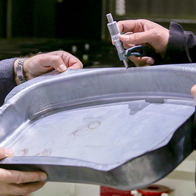
DSF-M2-4000, 400 Ton Servo PressPrecision Metal Forming company, Ultraform Industries, based in Romeo, MI, USA, installed an AIDA DSF-M2-4000, 400 ton DSF Series Servo Press from AIDA-America in early 2016. Ultraform uses the press to stamp various parts for the automotive industry, including AHSS and safety parts.
"We can do more on it than on a conventional mechanical stamping press", says Don Frattaroli, president of Ultraform. Chris Hoffman, Process Engineer for Ultraform stated, "Right now on the servo press, we're running about 54 strokes per minute. The best we could do on our mechanical press was 32 spm."
Frequently Asked Questions
 Answers to Your Questions about AIDA and Press Related Topics
 We offer answers for all types of common questions - whether technical in nature or as simple as where to look for career opportunities. Examples of some questions are: What is HOLP? Where is the closest AIDA facility located? How can we get a copy of the manual for our AIDA press? What is reverse tonnage? Visit our frequently answered questions section to find answers to your questions.
View Frequently Asked QuestionsAIDA-Tech White Papers
 Technical Topics & Information
 Topics such as connections spacing, slide guiding systems, reverse tonnage and more, AIDA-Tech White papers offer information for a variety of technical subjects related to stamping presses and press operations.
View AIDA-Tech White PapersMetalforming Articles
 Articles from Industry Publications
 We maintain a library of metalforming articles from a variety of industry publications covering a wide range of topics centered on stamping and press operations. Topics include press technology, market trends, and press applications. Many of the articles collected here have been authored by or contributed to by AIDA associates.
View Metalforming ArticlesEducational Partners & Resources
 Research and Development
 Not only does AIDA invest 5% of annual revenue towards internal research and development, but AIDA also actively seeks and participates in research with educational institutions such as the Center for Precision Forming (OSU), Institut für Umformtechnik, Edison Welding and others.
More About Educational PartnersApplications Studies & Die Trials
 Schedule an Application Review or Die Trial, Today
 Application studies and die trials provided by AIDA prove, with your own dies and part drawings, how AIDA stamping press technology can have multiple benefits to your manufacturing operations, including increased production rates, higher quality parts, reduced scrap, and reduced maintenance.
Applications Studies & Die TrialsServoFormer Application Training
 Servo Press Controls Training
 AIDA is a partner for success in understanding and applying servo press flexibility to your opperations. Our experienced Application Engineers will assist in working with your team to ensure top performance is achieved from your servo presses.
ServoFormer Application TrainingServo Press Optimization
Application Specific Solutions AIDA understands that in order to maximize the benefits that servo press technology can bring the operations must be optimized. AIDA provides on-the-floor stroke profile optimization for maximum productivity.
Servo Press OptimizationStamping Press Technology
 Industry Leading Forming Systems
 For over 100 years AIDA has been developing and manufacturing specialized metalforming products like metal stamping presses and related automation equipment, such as transfers, robots, and feeders. AIDA's exclusive stamping press technology is used throughout our wide range of presses, from 30 through 4,000 tons capacity.
Stamping Press TechnologyServo Press Technology
 The Most Experienced Servo Press Builder
 AIDA introduced the world's first direct drive servo stamping presses two decades ago. Since that time, AIDA has continued to maintain the position of technology leader in developing servoforming presses. AIDA DSF Series (Direct Drive Servo Former) servo presses represent the pinnacle of advanced engineering and manufacturing in the metalforming and stamping press industries.
Servo Press TechnologyTerms & Glossary
 Operations, Components, & Press Industry Terminology
 A variety of functions may be performed by many different types of presses, depending upon the tooling. Typical press operations and other terms referring to press features and functions, as well as basic press characteristics and designs are explained in this section of our website.
View Terms & GlossaryUser Testimonials
Batesville Tool & Die
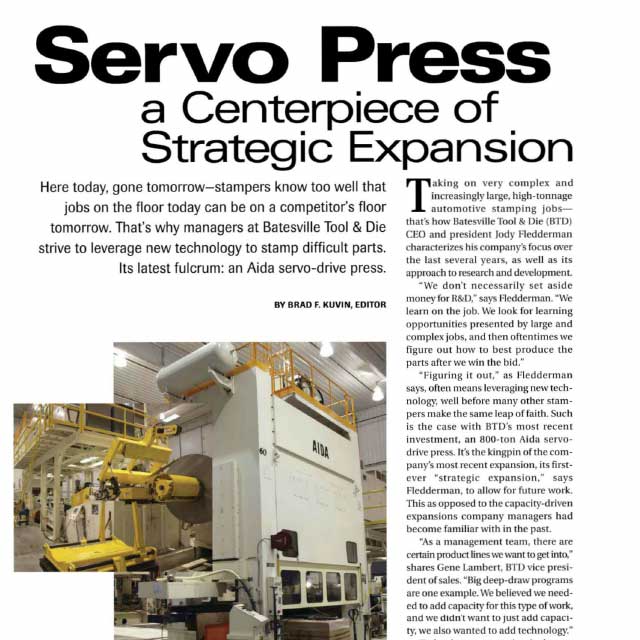 800 Ton Progressive Die Servo Press
 "We believed we needed to add capacity for this type of work, and we didn't want to just add capacity, we also wanted to add technology."
View User TestimonialMidway Products
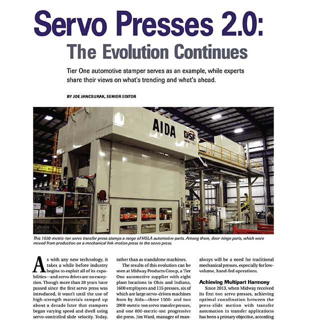 1,500 Ton Servo Presses and Transfer System
 "With servo drives, the contact and draw velocity area infinitely variable, enabling dynamic motion profiles with multiple slow-down windows to allow the transfer system time to do its job. We're able to achieve this with the help of our equipment vendor, AIDA-America, who has, over the years, provided many rounds of training for our programmers and operators to ensure optimization."
View User TestimonialOmex Manufacturing ULC
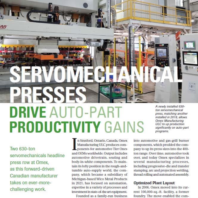 630 Ton Progressive Die Servo Press
 "We've just finished trialing an automotive-part program that previously ran at 25 strokes/min. We monitored the energy when forming at that rate, and by using pendulum motion to significantly cut back the dead (nonforming) cycle, we easily reached 40 strokes/min."
View User TestimonialUltraform Industries
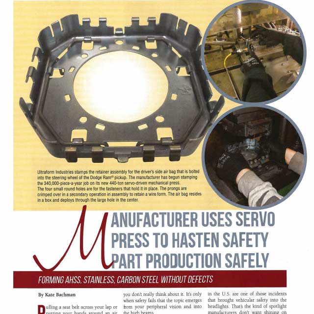 400 Ton Progressive Die Servo Press
 "Right now on the servo press, we're running about 54 strokes per minute. The best we could do on our mechanical press was 32."
View User Testimonial