Unitized Frame Servo Press DSF-N1 Single Point, From 80 - 300 Tons

Press Information
Press Information & Overview
Single Point Unitized Frame Press Equipped with DSF Direct Drive Servo
- Same Mechanical Drive Train of the tried and true NS1 Mechanical Press
- AIDA HOLP
- ECO Power Management System
- AIDA DSF Direct Drive Servo Motor
The AIDA DSF-N1 Direct Drive Unitized Frame Servo Press marries the successful mechanical design of the NS1 Series Mechanical Unitized Frame press with AIDA's DSF Direct Drive Servo. This combines the rigidity of a unitized frame with the flexibility of the freely programmable servo motion.
Request More InformationPress Features
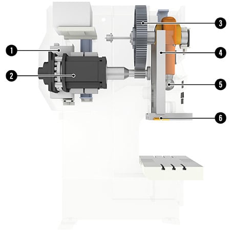
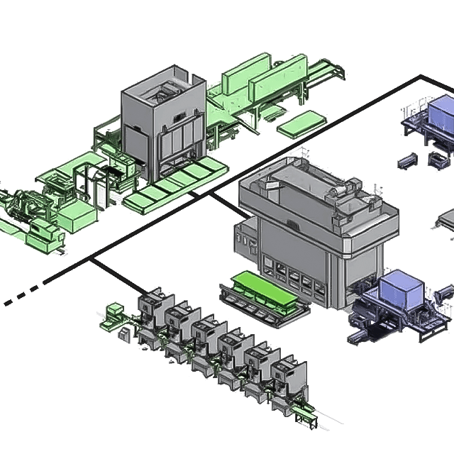
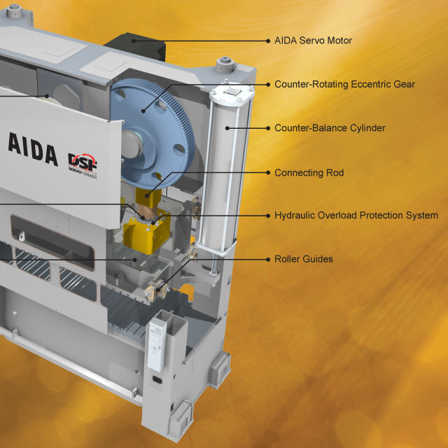
AIDA DSF-N1 Structure
- E.C.O. Servo Press Energy Management System
![E.C.O. Servo Press Energy Management System]()
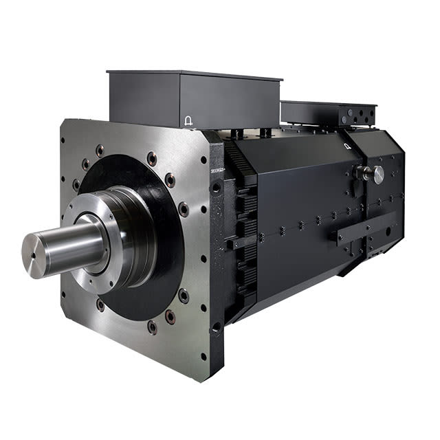
- AIDA Servo Motor
![AIDA Servo Motor for Stamping Presses]()
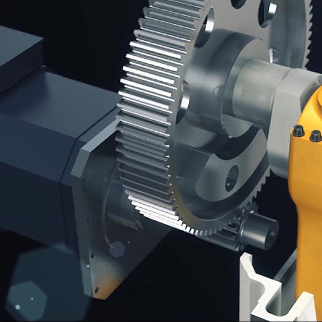
- Hardened & ground pinion and ground main gear
![AIDA ground main gear]()
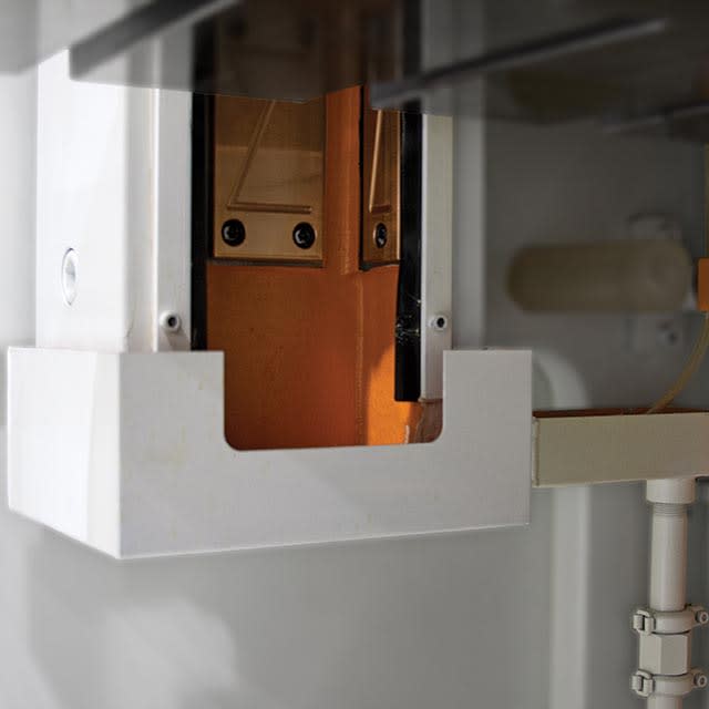
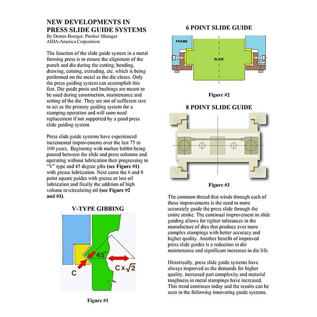
- 6-Point Slide Guide System
![6-Point Slide Guide System]()
- Hydraulic Overload Protection System (HOLP)
![AIDA Hydraulic Overload Protection System (HOLP)]()
- Recirculating Oil Lubrication System
![Recirculating Oil Lubrication System]()

6-Point Slide Guide System
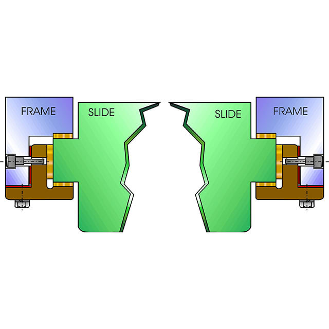 Simple, Yet Effective Slide Guide System for Stamping Presses
Extra-long gibs with extensions on the slide minimize "tipping" of the slide within the guides and provide superior off-center guiding vs. industry standard
AIDA Servo Motors
 The Most Powerful Servo Motors Available for Stamping Presses
Direct drive servo motors, driving the industry's leading servo presses. Low speed, high torque, specifically manufactured for stamping press applications using standard press drive train design.
Ball and Socket Connections
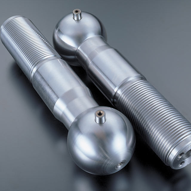 Improved Design When Compared to Wrist Pin Connections
Eliminate one of the largest maintenance costs of a stamping press: the wrist pin slide connections. Designed to withstand the rigors of heavy stamping.
High Precision Drivetrain System
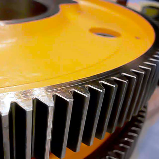 Utilizes Hardened and Ground Pinion and Main Gears
Provides industry minimal backlash resulting in improved press accuracy. Integrated hardened pinion minimizes required gear diameters and related drivetrain inertia.
HOLP
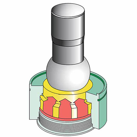 Hydraulic Overload Protection System
AIDA's press technology - the industry's fastest protection system. When overload occurs, oil evacuates 360 degrees around the ball seat with minimum oil flow resistance as compared to conventional systems
Recirculating Oil Lubrication System
 Providing Clean Oil in Metered Amounts to all Bearing Points
Oil from all lube points is captured, filtered, and recirculated. Bearing points are monitored to ensure that they receive the correct amount of oil.
Servo Press Control Features
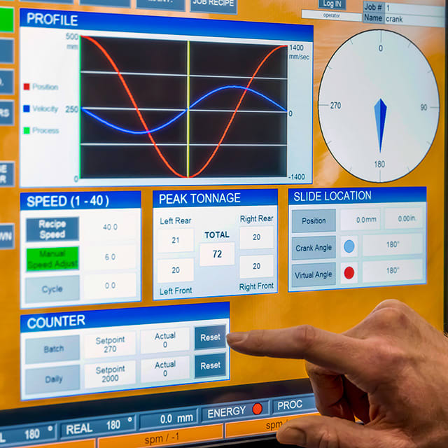
Mitsubishi Controls
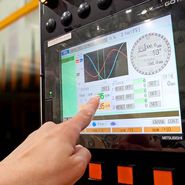 Servo Press Control Platform
Provides full functionality at an affordable price. Mitsubishi PLC with AIDA motion controller for precise control of your servo press.
More about Mitsubishi ControlsCNC Handwheel Control
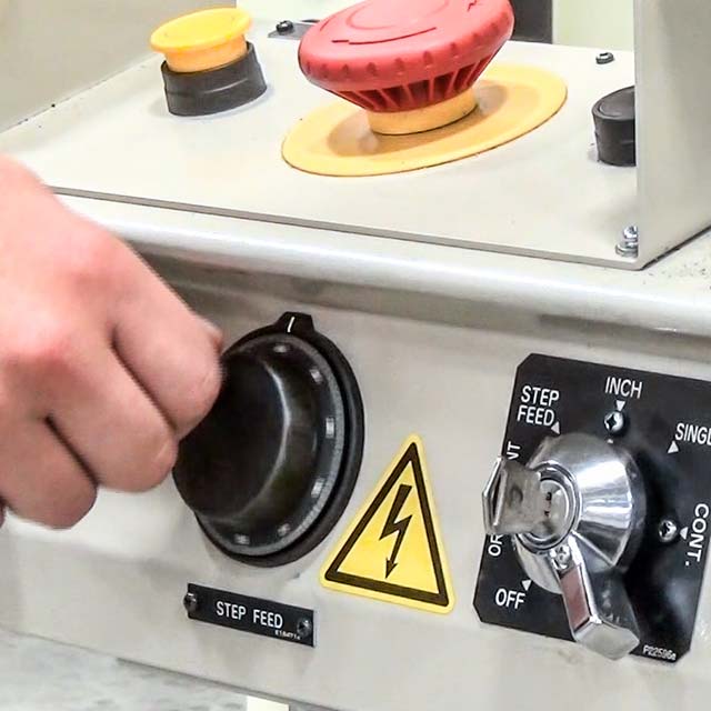 T-Stand Mounted Type
 Precise control of your servo press at your fingertips. The answer to die set-up and try-out operations. Step Feed Mode, controlled by the handwheel, allows press operators to cycle the press at below 1 spm.
More About CNC Handwheel ControlE.C.O. System
The most efficient servo press energy management system available. The AIDA system stores energy in long life capacitor system (rated over 20 years) to optimize energy consumption.
More About E.C.O. SystemProgrammable Slide Motions
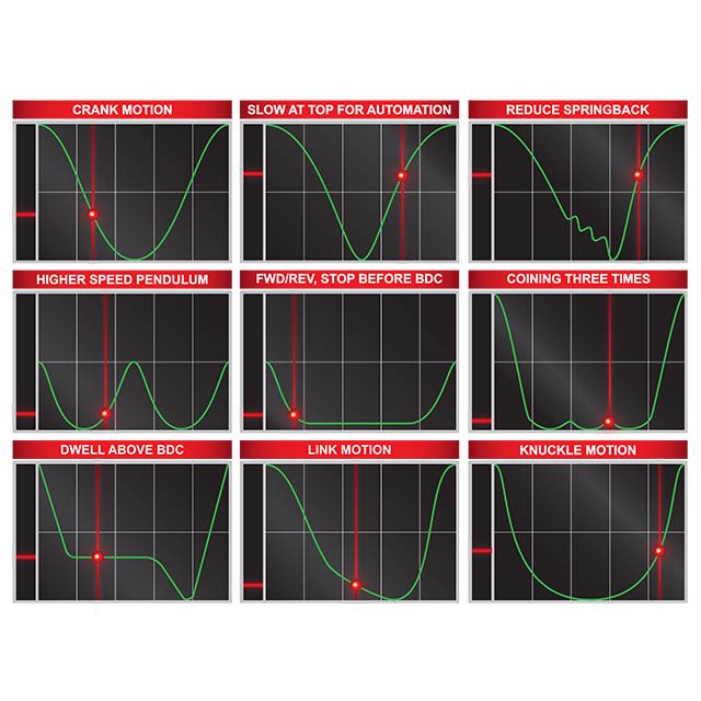 Complete Control of Position, Velocity, Dwell & Beyond
Optimized servo press slide motion profiles maximize metal stamping productivity and improve part quality.
Press Specifications
DSF-N1 Servo Press Specifications
| 80 Ton | 110 Ton |
| 150 Ton | 200 Ton |
| 300 Ton | Specifications PDF |
| 80 - 300 Ton | Specifications PDF |
DSF-N1-800, 80 Ton Unitized Frame Servo Press Specifications
| DSF-N1 MODELS | |||||
| Press Technical Data | Unit | DSF-N1-800 | |||
| Tonnage Capacity | kN | 800 | |||
| U.S. Ton | 88 | ||||
| Rating Point | mm | 5.0 | |||
| in. | 0.197 | ||||
| Working Energy | J | 4000 | |||
| in-ton | 18 | ||||
| Slide Stroke Length (maximum) | mm | 160 | |||
| in. | 6.30 | ||||
| SPM @ Full Stroke Length (no load) | spm | 1 - 80 | |||
| Stroke Length, Fully Adjustable * (See AIDA for further examples) | mm | 50 | 75 | 100 | 125 |
| in. | 2.0 | 3.0 | 3.9 | 4.9 | |
| SPM @ Stroke Length Above (no load) | spm | 125 | 115 | 95 | 85 |
| Die Height (SDAU) | mm | 320 | |||
| in. | 12.60 | ||||
| Slide Adjustment | mm | 80 | |||
| in. | 3.15 | ||||
| Slide Area (LR x FB) | mm | 700 x 460 | |||
| in. | 27.6 x 18.1 | ||||
| Bolster Area (LR x FB) | mm | 900 x 600 | |||
| in. | 35.4 x 23.6 | ||||
| Bolster Thickness | mm | 140 | |||
| in. | 5.5 | ||||
| Side Opening ** | mm | 440 x 300 (250) | |||
| in. | 17.3 x 11.8 (9.8) | ||||
| Max. Upper Die Weight | kg | 300 | |||
| lbs. | 661 | ||||
| Main Motor (SERVO) | kW | 38 | |||
| hp | 50 | ||||
| Power Supply Capacity | kVA | 21 | |||
| Required Air Pressure | MPa | 0.5 | |||
| psi | 73 | ||||
| Foundation Bolt Position (LR x FB) | mm | 1220 x 1200 | |||
| in. | 48.0 x 47.2 | ||||
| Bed Opening Dimension (LR x FB) | mm | 1036 x 280 | |||
| in. | 40.8 x 11.0 | ||||
| Inside Frame Dimension | mm | 878 | |||
| in. | 34.6 | ||||
| Press Foot to Top of Bolster (without mounts) | mm | 900 | |||
| in. | 35.4 | ||||
| Overall Dimension (LR x FB) | mm | 1500 x 2160 | |||
| in. | 59.1 x 85.0 | ||||
| Approx. Overall Height (without mounts) | mm | 2965 | |||
| in. | 117 | ||||
| * Dimensions shown in inches rounded to the nearest tenth. ** Dimensions in parentheses ( ) show the height above the bolster. | |||||
DSF-N1-1100, 110 Ton Unitized Frame Servo Press Specifications
| DSF-N1 MODELS | |||||
| Press Technical Data | Unit | DSF-N1-1100 | |||
| Tonnage Capacity | kN | 1100 | |||
| U.S. Ton | 121 | ||||
| Rating Point | mm | 5.0 | |||
| in. | 0.197 | ||||
| Working Energy | J | 4600 | |||
| in-ton | 20 | ||||
| Slide Stroke Length (maximum) | mm | 180 | |||
| in. | 7.09 | ||||
| SPM @ Full Stroke Length (no load) | spm | 1 - 70 | |||
| Stroke Length, Fully Adjustable * (See AIDA for further examples) | mm | 50 | 75 | 100 | 125 |
| in. | 2.0 | 3.0 | 3.9 | 4.9 | |
| SPM @ Stroke Length Above (no load) | spm | 130 | 110 | 95 | 85 |
| Die Height (SDAU) | mm | 350 | |||
| in. | 13.78 | ||||
| Slide Adjustment | mm | 90 | |||
| in. | 3.54 | ||||
| Slide Area (LR x FB) | mm | 800 x 520 | |||
| in. | 31.5 x 20.5 | ||||
| Bolster Area (LR x FB) | mm | 1000 x 680 | |||
| in. | 39.4 x 26.8 | ||||
| Bolster Thickness | mm | 155 | |||
| in. | 6.1 | ||||
| Side Opening ** | mm | 500 x 320 (270) | |||
| in. | 19.7 x 12.6 (10.6) | ||||
| Max. Upper Die Weight | kg | 350 | |||
| lbs. | 772 | ||||
| Main Motor (SERVO) | kW | 40 | |||
| hp | 55 | ||||
| Power Supply Capacity | kVA | 21 | |||
| Required Air Pressure | MPa | 0.5 | |||
| psi | 73 | ||||
| Foundation Bolt Position (LR x FB) | mm | 1344 x 1310 | |||
| in. | 52.9 x 51.6 | ||||
| Bed Opening Dimension (LR x FB) | mm | 1160 x 320 | |||
| in. | 45.7 x 12.6 | ||||
| Inside Frame Dimension | mm | 950 | |||
| in. | 37.4 | ||||
| Press Foot to Top of Bolster (without mounts) | mm | 900 | |||
| in. | 35.4 | ||||
| Overall Dimension (LR x FB) | mm | 1868 x 2234 | |||
| in. | 73.5 x 88.0 | ||||
| Approx. Overall Height (without mounts) | mm | 3040 | |||
| in. | 120 | ||||
| * Dimensions shown in inches rounded to the nearest tenth. ** Dimensions in parentheses ( ) show the height above the bolster. | |||||
DSF-N1-1500, 150 Ton Unitized Frame Servo Press Specifications
| DSF-N1 MODELS | |||||
| Press Technical Data | Unit | DSF-N1-1500 | |||
| Tonnage Capacity | kN | 1500 | |||
| U.S. Ton | 165 | ||||
| Rating Point | mm | 6.0 | |||
| in. | 0.236 | ||||
| Working Energy | J | 7900 | |||
| in-ton | 35 | ||||
| Slide Stroke Length (maximum) | mm | 200 | |||
| in. | 7.87 | ||||
| SPM @ Full Stroke Length (no load) | spm | 1 - 60 | |||
| Stroke Length, Fully Adjustable * (See AIDA for further examples) | mm | 50 | 75 | 100 | 125 |
| in. | 2.0 | 3.0 | 3.9 | 4.9 | |
| SPM @ Stroke Length Above (no load) | spm | 120 | 102 | 88 | 79 |
| Die Height (SDAU) | mm | 400 | |||
| in. | 15.75 | ||||
| Slide Adjustment | mm | 100 | |||
| in. | 3.94 | ||||
| Slide Area (LR x FB) | mm | 900 x 580 | |||
| in. | 35.4 x 22.8 | ||||
| Bolster Area (LR x FB) | mm | 1150 x 760 | |||
| in. | 45.3 x 29.9 | ||||
| Bolster Thickness | mm | 165 | |||
| in. | 6.5 | ||||
| Side Opening ** | mm | 560 x 380 (330) | |||
| in. | 22.0 x 15.0 (13) | ||||
| Max. Upper Die Weight | kg | 500 | |||
| lbs. | 1102 | ||||
| Main Motor (SERVO) | kW | 55 | |||
| hp | 75 | ||||
| Power Supply Capacity | kVA | 26 | |||
| Required Air Pressure | MPa | 0.5 | |||
| psi | 73 | ||||
| Foundation Bolt Position (LR x FB) | mm | 1525 x 1450 | |||
| in. | 60.0 x 57.1 | ||||
| Bed Opening Dimension (LR x FB) | mm | 1330 x 360 | |||
| in. | 52.4 x 14.2 | ||||
| Inside Frame Dimension | mm | 1100 | |||
| in. | 43.3 | ||||
| Press Foot to Top of Bolster (without mounts) | mm | 900 | |||
| in. | 35.4 | ||||
| Overall Dimension (LR x FB) | mm | 1820 x 2520 | |||
| in. | 71.7 x 99.2 | ||||
| Approx. Overall Height (without mounts) | mm | 3300 | |||
| in. | 130 | ||||
| * Dimensions shown in inches rounded to the nearest tenth. ** Dimensions in parentheses ( ) show the height above the bolster. | |||||
DSF-N1-2000, 200 Ton Unitized Frame Servo Press Specifications
| DSF-N1 MODELS | |||||
| Press Technical Data | Unit | DSF-N1-2000 | |||
| Tonnage Capacity | kN | 2000 | |||
| U.S. Ton | 220 | ||||
| Rating Point | mm | 6.0 | |||
| in. | 0.236 | ||||
| Working Energy | J | 13100 | |||
| in-ton | 58 | ||||
| Slide Stroke Length (maximum) | mm | 250 | |||
| in. | 9.84 | ||||
| SPM @ Full Stroke Length (no load) | spm | 1 - 50 | |||
| Stroke Length, Fully Adjustable * (See AIDA for further examples) | mm | 50 | 75 | 100 | 125 |
| in. | 2.0 | 3.0 | 3.9 | 4.9 | |
| SPM @ Stroke Length Above (no load) | spm | 108 | 95 | 85 | 75 |
| Die Height (SDAU) | mm | 450 | |||
| in. | 17.72 | ||||
| Slide Adjustment | mm | 110 | |||
| in. | 4.33 | ||||
| Slide Area (LR x FB) | mm | 1000 x 650 | |||
| in. | 39.4 x 25.6 | ||||
| Bolster Area (LR x FB) | mm | 1250 x 840 | |||
| in. | 49.2 x 33.1 | ||||
| Bolster Thickness | mm | 180 | |||
| in. | 7.1 | ||||
| Side Opening ** | mm | 620 x 420 (370) | |||
| in. | 24.4 x 16.5 (14.6) | ||||
| Max. Upper Die Weight | kg | 1000 | |||
| lbs. | 2205 | ||||
| Main Motor (SERVO) | kW | 120 | |||
| hp | 160 | ||||
| Power Supply Capacity | kVA | 35 | |||
| Required Air Pressure | MPa | 0.5 | |||
| psi | 73 | ||||
| Foundation Bolt Position (LR x FB) | mm | 1655 x 1590 | |||
| in. | 65.2 x 62.6 | ||||
| Bed Opening Dimension (LR x FB) | mm | 1450 x 460 | |||
| in. | 57.1 x 18.1 | ||||
| Inside Frame Dimension | mm | 1300 | |||
| in. | 51.2 | ||||
| Press Foot to Top of Bolster (without mounts) | mm | 1000 | |||
| in. | 39.4 | ||||
| Overall Dimension (LR x FB) | mm | 2005 x 2175 | |||
| in. | 78.9 x 85.6 | ||||
| Approx. Overall Height (without mounts) | mm | 3795 | |||
| in. | 149 | ||||
| * Dimensions shown in inches rounded to the nearest tenth. ** Dimensions in parentheses ( ) show the height above the bolster. | |||||
DSF-N1-3000, 300 Ton Unitized Frame Servo Press Specifications
| DSF-N1 MODELS | |||||
| Press Technical Data | Unit | DSF-N1-3000 | |||
| Tonnage Capacity | kN | 3000 | |||
| U.S. Ton | 330 | ||||
| Rating Point | mm | 5.0 | |||
| in. | 0.197 | ||||
| Working Energy | J | 18000 | |||
| in-ton | 80 | ||||
| Slide Stroke Length (maximum) | mm | 300 | |||
| in. | 11.81 | ||||
| SPM @ Full Stroke Length (no load) | spm | 1 - 35 | |||
| Stroke Length, Fully Adjustable * (See AIDA for further examples) | mm | 300 | 240 | 180 | |
| in. | 11.8 | 9.4 | 7.1 | ||
| SPM @ Stroke Length Above (no load) | spm | 35 | 41 | 50 | |
| Die Height (SDAU) | mm | 570 | |||
| in. | 22.44 | ||||
| Slide Adjustment | mm | 120 | |||
| in. | 4.72 | ||||
| Slide Area (LR x FB) | mm | 1300 x 900 | |||
| in. | 51.2 x 35.4 | ||||
| Bolster Area (LR x FB) | mm | 1500 x 1000 | |||
| in. | 59.1 x 39.4 | ||||
| Bolster Thickness | mm | 200 | |||
| in. | 7.9 | ||||
| Side Opening ** | mm | 1000 x 550 (530) | |||
| in. | 39.4 x 21.7 (20.9) | ||||
| Max. Upper Die Weight | kg | 1300 | |||
| lbs. | 2866 | ||||
| Main Motor (SERVO) | kW | 120 | |||
| hp | 160 | ||||
| Power Supply Capacity | kVA | 69 | |||
| Required Air Pressure | MPa | 0.5 | |||
| psi | 73 | ||||
| Foundation Bolt Position (LR x FB) | mm | 1740 x 1600 | |||
| in. | 68.5 x 63.0 | ||||
| Bed Opening Dimension (LR x FB) | mm | 620 x 620 | |||
| in. | 24.4 x 24.4 | ||||
| Inside Frame Dimension | mm | 1536 | |||
| in. | 60.5 | ||||
| Press Foot to Top of Bolster (without mounts) | mm | 1120 | |||
| in. | 44.1 | ||||
| Overall Dimension (LR x FB) | mm | 2500 x 3100 | |||
| in. | 98.4 x 122.0 | ||||
| Approx. Overall Height (without mounts) | mm | 4745 | |||
| in. | 187 | ||||
| * Dimensions shown in inches rounded to the nearest tenth. ** Dimensions in parentheses ( ) show the height above the bolster. | |||||
DSF-N1, 80 - 300 Ton Unitized Frame Servo Press Specifications
| DSF-N1 MODELS | ||||||||||||||||||||
| Press Technical Data | Unit | DSF-N1-800 | DSF-N1-1100 | DSF-N1-1500 | DSF-N1-2000 | DSF-N1-3000 | ||||||||||||||
| Tonnage Capacity | kN | 800 | 1100 | 1500 | 2000 | 3000 | ||||||||||||||
| U.S. Ton | 88 | 121 | 165 | 220 | 330 | |||||||||||||||
| Rating Point | mm | 5.0 | 5.0 | 6.0 | 6.0 | 5.0 | ||||||||||||||
| in. | 0.197 | 0.197 | 0.236 | 0.236 | 0.197 | |||||||||||||||
| Working Energy | J | 4000 | 4600 | 7900 | 13100 | 18000 | ||||||||||||||
| in-ton | 18 | 20 | 35 | 58 | 80 | |||||||||||||||
| Slide Stroke Length (maximum) | mm | 160 | 180 | 200 | 250 | 300 | ||||||||||||||
| in. | 6.30 | 7.09 | 7.87 | 9.84 | 11.81 | |||||||||||||||
| SPM @ Full Stroke Length (no load) | spm | 1 - 80 | 1 - 70 | 1 - 60 | 1 - 50 | 1 - 35 | ||||||||||||||
| Stroke Length, Fully Adjustable * (See AIDA for further examples) | mm | 50 | 75 | 100 | 125 | 50 | 75 | 100 | 125 | 50 | 75 | 100 | 125 | 50 | 75 | 100 | 125 | 300 | 240 | 180 |
| in. | 2.0 | 3.0 | 3.9 | 4.9 | 2.0 | 3.0 | 3.9 | 4.9 | 2.0 | 3.0 | 3.9 | 4.9 | 2.0 | 3.0 | 3.9 | 4.9 | 11.8 | 9.4 | 7.1 | |
| SPM @ Stroke Length Above (no load) | spm | 125 | 115 | 95 | 85 | 130 | 110 | 95 | 85 | 120 | 102 | 88 | 79 | 108 | 95 | 85 | 75 | 35 | 41 | 50 |
| Die Height (SDAU) | mm | 320 | 350 | 400 | 450 | 570 | ||||||||||||||
| in. | 12.60 | 13.78 | 15.75 | 17.72 | 22.44 | |||||||||||||||
| Slide Adjustment | mm | 80 | 90 | 100 | 110 | 120 | ||||||||||||||
| in. | 3.15 | 3.54 | 3.94 | 4.33 | 4.72 | |||||||||||||||
| Slide Area (LR x FB) | mm | 700 x 460 | 800 x 520 | 900 x 580 | 1000 x 650 | 1300 x 900 | ||||||||||||||
| in. | 27.6 x 18.1 | 31.5 x 20.5 | 35.4 x 22.8 | 39.4 x 25.6 | 51.2 x 35.4 | |||||||||||||||
| Bolster Area (LR x FB) | mm | 900 x 600 | 1000 x 680 | 1150 x 760 | 1250 x 840 | 1500 x 1000 | ||||||||||||||
| in. | 35.4 x 23.6 | 39.4 x 26.8 | 45.3 x 29.9 | 49.2 x 33.1 | 59.1 x 39.4 | |||||||||||||||
| Bolster Thickness | mm | 140 | 155 | 165 | 180 | 200 | ||||||||||||||
| in. | 5.5 | 6.1 | 6.5 | 7.1 | 7.9 | |||||||||||||||
| Side Opening ** | mm | 440 x 300 (250) | 500 x 320 (270) | 560 x 380 (330) | 620 x 420 (370) | 1000 x 550 (530) | ||||||||||||||
| in. | 17.3 x 11.8 (9.8) | 19.7 x 12.6 (10.6) | 22.0 x 15.0 (13) | 24.4 x 16.5 (14.6) | 39.4 x 21.7 (20.9) | |||||||||||||||
| Max. Upper Die Weight | kg | 300 | 350 | 500 | 1000 | 1300 | ||||||||||||||
| lbs. | 661 | 772 | 1102 | 2205 | 2866 | |||||||||||||||
| Main Motor (SERVO) | kW | 38 | 40 | 55 | 120 | 120 | ||||||||||||||
| hp | 50 | 55 | 75 | 160 | 160 | |||||||||||||||
| Power Supply Capacity | kVA | 21 | 21 | 26 | 35 | 69 | ||||||||||||||
| Required Air Pressure | MPa | 0.5 | 0.5 | 0.5 | 0.5 | 0.5 | ||||||||||||||
| psi | 73 | 73 | 73 | 73 | 73 | |||||||||||||||
| Foundation Bolt Position (LR x FB) | mm | 1220 x 1200 | 1344 x 1310 | 1525 x 1450 | 1655 x 1590 | 1740 x 1600 | ||||||||||||||
| in. | 48.0 x 47.2 | 52.9 x 51.6 | 60.0 x 57.1 | 65.2 x 62.6 | 68.5 x 63.0 | |||||||||||||||
| Bed Opening Dimension (LR x FB) | mm | 1036 x 280 | 1160 x 320 | 1330 x 360 | 1450 x 460 | 620 x 620 | ||||||||||||||
| in. | 40.8 x 11.0 | 45.7 x 12.6 | 52.4 x 14.2 | 57.1 x 18.1 | 24.4 x 24.4 | |||||||||||||||
| Inside Frame Dimension | mm | 878 | 950 | 1100 | 1300 | 1536 | ||||||||||||||
| in. | 34.6 | 37.4 | 43.3 | 51.2 | 60.5 | |||||||||||||||
| Press Foot to Top of Bolster (without mounts) | mm | 900 | 900 | 900 | 1000 | 1120 | ||||||||||||||
| in. | 35.4 | 35.4 | 35.4 | 39.4 | 44.1 | |||||||||||||||
| Overall Dimension (LR x FB) | mm | 1500 x 2160 | 1868 x 2234 | 1820 x 2520 | 2005 x 2175 | 2500 x 3100 | ||||||||||||||
| in. | 59.1 x 85.0 | 73.5 x 88.0 | 71.7 x 99.2 | 78.9 x 85.6 | 98.4 x 122.0 | |||||||||||||||
| Approx. Overall Height (without mounts) | mm | 2965 | 3040 | 3300 | 3795 | 4745 | ||||||||||||||
| in. | 117 | 120 | 130 | 149 | 187 | |||||||||||||||
| * Dimensions shown in inches rounded to the nearest tenth. ** Dimensions in parentheses ( ) show the height above the bolster. | ||||||||||||||||||||
Technical Resources
Frequently Asked Questions
 Answers to Your Questions about AIDA and Press Related Topics
 We offer answers for all types of common questions - whether technical in nature or as simple as where to look for career opportunities. Examples of some questions are: What is HOLP? Where is the closest AIDA facility located? How can we get a copy of the manual for our AIDA press? What is reverse tonnage? Visit our frequently answered questions section to find answers to your questions.
View Frequently Asked QuestionsAIDA-Tech White Papers
 Technical Topics & Information
 Topics such as connections spacing, slide guiding systems, reverse tonnage and more, AIDA-Tech White papers offer information for a variety of technical subjects related to stamping presses and press operations.
View AIDA-Tech White PapersMetalforming Articles
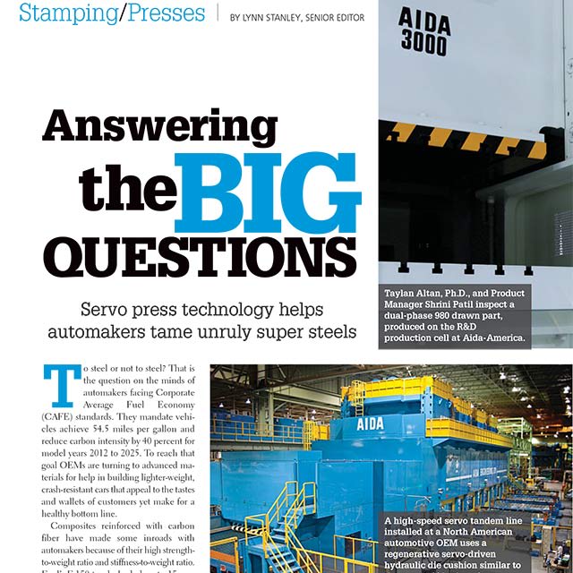 Articles from Industry Publications
 We maintain a library of metalforming articles from a variety of industry publications covering a wide range of topics centered on stamping and press operations. Topics include press technology, market trends, and press applications. Many of the articles collected here have been authored by or contributed to by AIDA associates.
View Metalforming ArticlesEducational Partners & Resources
 Research and Development
 Not only does AIDA invest 5% of annual revenue towards internal research and development, but AIDA also actively seeks and participates in research with educational institutions such as the Center for Precision Forming (OSU), Institut für Umformtechnik, Edison Welding and others.
More About Educational PartnersApplications Studies & Die Trials
 Schedule an Application Review or Die Trial, Today
 Application studies and die trials provided by AIDA prove, with your own dies and part drawings, how AIDA stamping press technology can have multiple benefits to your manufacturing operations, including increased production rates, higher quality parts, reduced scrap, and reduced maintenance.
Applications Studies & Die TrialsServoFormer Application Training
 Servo Press Controls Training
 AIDA is a partner for success in understanding and applying servo press flexibility to your opperations. Our experienced Application Engineers will assist in working with your team to ensure top performance is achieved from your servo presses.
ServoFormer Application TrainingServo Press Optimization
Application Specific Solutions AIDA understands that in order to maximize the benefits that servo press technology can bring the operations must be optimized. AIDA provides on-the-floor stroke profile optimization for maximum productivity.
Servo Press OptimizationStamping Press Technology
 Industry Leading Forming Systems
 For over 100 years AIDA has been developing and manufacturing specialized metalforming products like metal stamping presses and related automation equipment, such as transfers, robots, and feeders. AIDA's exclusive stamping press technology is used throughout our wide range of presses, from 30 through 4,000 tons capacity.
Stamping Press TechnologyServo Press Technology
 The Most Experienced Servo Press Builder
 AIDA introduced the world's first direct drive servo stamping presses two decades ago. Since that time, AIDA has continued to maintain the position of technology leader in developing servoforming presses. AIDA DSF Series (Direct Drive Servo Former) servo presses represent the pinnacle of advanced engineering and manufacturing in the metalforming and stamping press industries.
Servo Press TechnologyTerms & Glossary
 Operations, Components, & Press Industry Terminology
 A variety of functions may be performed by many different types of presses, depending upon the tooling. Typical press operations and other terms referring to press features and functions, as well as basic press characteristics and designs are explained in this section of our website.
View Terms & Glossary